I want to use bladeRF with PocketSDR AP
PocketSDR AP
PocketSDR released on GitHub is a package that receives and processes navigation satellite signals by software defined radio (SDR). It consists of hardware schematic using Maxim MAX2771 and the AP (application)software written in Python, and sample data observed by this hardware. We can easily experience the actual signal processing with PocketSDR.
- Awesome PocketSDR (snapshot reception)
- Awesome PocketSDR (reducing processing time with FFTW)
- Awesome PocketSDR (L6 band signal decode)
- Awesome PocketSDR (pocket_trk)
- Awesome PocketSDR (pocket_acq)
PocketSDR hardware
A schematic editor file (the extension is sch) and a wiring pattern file (the extension is brd) for the CAD (computer aided design) software Autodesk EAGLE are attached to PocketSDR. This EAGLE can be used free of charge under certain conditions. By reading the sch file and brd file with EAGLE, you can output the Gerber data and metal mask data required for board ordering.
I am also preparing a reflow oven (board heater) and aiming to make PocketSDR hardware, but the MAX2771 is currently unavailable. I’m also interested in Maxim MAX2769, but it’s not available either.
However, PocketSDR APs are designed to be hardware independent. Therefore, connecting a navigation satellite antenna to the bladeRF x40 of your SDR hardware, observing the signal, and we can process the satellite signals with the PocketSDR AP.
Actually, I didn’t get very good results, but I was able to confirm the minimum. Eventually I would like to use PocketSDR hardware.
Equipment configuration
The hardware equipment used here is as follows. This experiment will be performed using one port of the signal splitter. The bynav C1-FS receiver and u-blox F9P receiver / Drogger VRSC receiver are connected to the remaining signal splitter ports.
- Nuand bladeRF x40 (300 MHz-3.8 GHz, 12-bit 40MSPS, 40KLE Altera Cyclone 4E FPGA)
- DFRobot LattePanda Alpha 800s (Intel Core m3-8100y, 8GB LPDDR3) + NVMe SSD 1TB
- Beitian BT-200(L1-band, L2-band, L5-band, L6-band antenna)
- Coaxial cable 20 m
- InStock Wireless GPS410(4 port signal splitter)
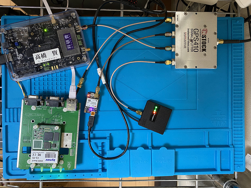
I have Ubuntu 20.04.4 LTS installed on LattePanda. The bladeRF used here is an old product, but I think it can be used with the current product bladeRF 2.0 micro as well. In addition, the version of bladeRF by typing bladeRF-cli -i is as follows. The option -i represents the use of interactive mode.
bladeRF> version

  bladeRF-cli version:        1.8.0-git-c8320f71-ppafocal
  libbladeRF version:         2.2.1-git-c8320f71-ppafocal

  Firmware version:           2.3.2
  FPGA version:               0.11.0 (configured by USB host)
GPS L1 C/A signal observation
The center frequency of the GPS L1 C/A signal is 1.57542 GHz. First, we need deciding the sampling frequency and bandwidth for bladeRF. The measurement samples included in PocketSDR consists of the baseband sampling and the low-IF (intermediate frequency) sampling. Here, the sampling frequency of 4 MHz and the bandwidth of 3 MHz are used by referring to the PocketSDR measurement sample (sampling frequency of 4 MHz and bandwidth of 2.5 MHz) of L1_20211202_084700_4 MHz_IQ.bin. The bandwidth that bladeRF accepts is either 1.5 MHz, 2.5 MHz, 2.75 MHz, 3 MHz, 3.84 MHz, 5 MHz, 5.5 MHz, 6 MHz, 7 MHz, 8.75 MHz, 10 MHz, 12 MHz, 14 MHz, 20 MHz, or 28 MHz.
Actually, we turns off AGC (automatic gain control), and set the gain to the maximum of 60 dB. After performing DC offset correction, we records satellite radio signals for 0.1 seconds. Here, bladeRF-cli -i is used to set bladeRF interactively, but it is also possible to save this to a file and execute it in batch with the -s option.
set frequency rx 1.57542g
set bandwidth rx 3m
set samplerate rx 4m
set agc rx off
set gain rx 60
cal lms
cal dc rx
rx config format=bin n=400k file=ch.bin
rx start
rx wait
Immediately you will be prompted with bladeRF> and the observation file ch.bin will be saved.
Importing the observation data to bladeRF
We need modifications of the source codes of sdr_func.py and pocket_trk.py in the python directory to load this observation file into the PocketSDR AP. The function to be modified is read_data ().
sdr_func.py
def read_data(file, fs, IQ, T, toff=0.0, sdrname='pocketsdr'):
    off = int(fs * toff * IQ)
    cnt = int(fs * T * IQ) if T > 0.0 else -1 # all if T=0.0

    if sdrname == 'pocketsdr':
        dt   = 'int8'  # data type
        div  =  1      # divisor of data
        qsgn = -1      # Q sign inverted in MAX2771
    elif sdrname == 'bladerf':
        dt   = 'int16' # data type
        div  = 256     # divisor of data
        qsgn = 1       # Q sign
    else:
        raise ValueError('Please specify appropriate SDR.')

    raw = np.fromfile(file, dtype=dt, offset=off, count=cnt)

    if len(raw) < cnt:
        return np.array([], dtype='complex64')
    elif IQ == 1: # I-sampling
        return np.array(raw/div, dtype='complex64')
    else: # IQ-sampling
        return np.array(raw[0::2]/div + raw[1::2] * 1j*qsgn/div, dtype='complex64')
pocket_trk.py
def read_data(fp, N, IQ, buff, ix, sdrname = 'pocketsdr'):
    if sdrname == 'pocketsdr':
        dt   ='int8'   # data type
        ds   =  1      # data size
        div  =  1      # divisor of data
        qsgn = -1      # Q sign inverted in MAX2771
    elif sdrname == 'bladerf':
        dt   = 'int16' # data type
        ds   =   2     # data size
        div  = 256     # divisor of data
        qsgn =   1     # Q sign
    else:
        raise ValueError('Please specify appropriate SDR.')

    if fp == None:
        raw = np.frombuffer(sys.stdin.buffer.read(N * IQ * ds), dtype=dt)
    else:
        raw = np.frombuffer(fp.read(N * IQ * ds), dtype=dt)

    if len(raw) < N * IQ:
        return False
    elif IQ == 1: # I
        buff[ix:ix+N] = np.array(raw/div, dtype='complex64')
    else: # IQ
        buff[ix:ix+N] = np.array(raw[0::2]/div + raw[1::2]*1j*qsgn/div, dtype='complex64')
    return True
PocketSDR samples IQ (in-phase, quadrature) components in 2 bits each, while bladeRF samples them in 12 bits each. However, not of all bits were used in the observations with bladeRF.
Since PocketSDR AP reads the observation data with complex64, we can set the integer value read here directory to buff. However, in order to display it clearly in the PocketSDR AP user interface, the observation data of bladeRF is divided by 256 when we store them in buff.
Then, we modify pocket_ *.py so that we can choose an SDR as bladeRF with the -sdr option.
GPS L1 C/A signal processing
The observation file obtained in this way is processed the power spectral density confirmation, the signal acquisition, and the signal tracking.
First, let’s look at this power spectral density and histogram. Executing ./pocket_psd.py -f 4 -IQ -h -sdr bladerf ch.bin in the PocketSDR sample directory, and we can see them.
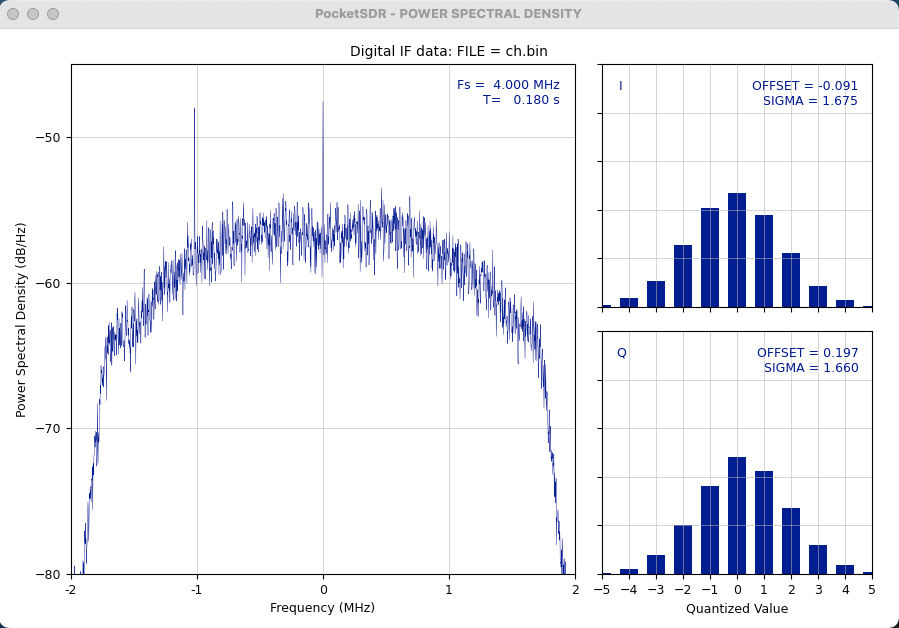
Comparing it with the spectrum in PocketSDR below, the spectrum does not have clear signal part.
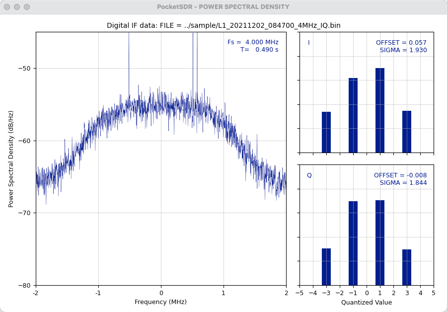
Both the IQ (in-phase, quadrature) components of the signal observed by bladeRF are Gauss-shaped, and it seems that they are operating well. However, in this histogram, it is desirable that the zero component does not appear if a signal is present, and there was no zero component in the PocketSDR histogram. In the Nuand forum, it is discussed to reduce the gain of RX VGA2 (reception variable gain amplifier 2) of bladeRF to 10 dB and add LNA (low noise amplifier). In my environment, when I lowered the VGA2 gain to 10 dB, the histogram was only direct current, so I set this VGA2 gain to the maximum of 28 dB. In order to use bladeRF for satellite signal observation, it seems necessary to add LNA.
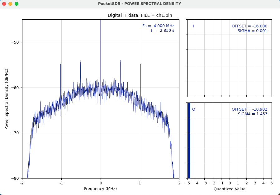
DC offset correction is especially important for bladeRF. If you do not run the cal lms and cal dc rx above, you will see a noticeable DC offset on the histogram, as shown below. I connected bladeRF to my Mac and tried to acquire data, but when I executed this DC offset correction command, a Segmentation Fault occurred and I could not correct it.
Next, we try capturing the L1 C / A signal. We execute pocket_acq.py for GPS PRN (pseudo random noise) numbers 1 to 32.
./pocket_acq.py -f 4 -prn 1-32 -sdr bladerf ch.bin
SIG= L1CA, PRN=   1, COFF=  0.92000 ms, DOP=  3115 Hz, C/N0= 33.8 dB-Hz
SIG= L1CA, PRN=   2, COFF=  0.43575 ms, DOP=  4107 Hz, C/N0= 46.2 dB-Hz
SIG= L1CA, PRN=   3, COFF=  0.87875 ms, DOP=  -424 Hz, C/N0= 34.0 dB-Hz
SIG= L1CA, PRN=   4, COFF=  0.32325 ms, DOP=  2525 Hz, C/N0= 33.5 dB-Hz
SIG= L1CA, PRN=   5, COFF=  0.00100 ms, DOP=  5000 Hz, C/N0= 39.7 dB-Hz
SIG= L1CA, PRN=   6, COFF=  0.01025 ms, DOP=  1701 Hz, C/N0= 47.6 dB-Hz
SIG= L1CA, PRN=   7, COFF=  0.98725 ms, DOP=  4268 Hz, C/N0= 38.1 dB-Hz
SIG= L1CA, PRN=   8, COFF=  0.97525 ms, DOP=  4034 Hz, C/N0= 34.0 dB-Hz
SIG= L1CA, PRN=   9, COFF=  0.33500 ms, DOP=   330 Hz, C/N0= 41.3 dB-Hz
SIG= L1CA, PRN=  10, COFF=  0.61250 ms, DOP=  4454 Hz, C/N0= 33.4 dB-Hz
SIG= L1CA, PRN=  11, COFF=  0.42475 ms, DOP=  3940 Hz, C/N0= 46.4 dB-Hz
SIG= L1CA, PRN=  12, COFF=  0.68625 ms, DOP=   527 Hz, C/N0= 38.8 dB-Hz
SIG= L1CA, PRN=  13, COFF=  0.94275 ms, DOP= -5000 Hz, C/N0= 34.2 dB-Hz
SIG= L1CA, PRN=  14, COFF=  0.00600 ms, DOP=  3484 Hz, C/N0= 34.5 dB-Hz
SIG= L1CA, PRN=  15, COFF=  0.22575 ms, DOP= -4452 Hz, C/N0= 34.2 dB-Hz
SIG= L1CA, PRN=  16, COFF=  0.75900 ms, DOP=  1574 Hz, C/N0= 35.4 dB-Hz
SIG= L1CA, PRN=  17, COFF=  0.63100 ms, DOP= -1015 Hz, C/N0= 38.5 dB-Hz
SIG= L1CA, PRN=  18, COFF=  0.92475 ms, DOP=  1880 Hz, C/N0= 34.4 dB-Hz
SIG= L1CA, PRN=  19, COFF=  0.01675 ms, DOP=  -933 Hz, C/N0= 42.7 dB-Hz
SIG= L1CA, PRN=  20, COFF=  0.55075 ms, DOP=  3894 Hz, C/N0= 44.1 dB-Hz
SIG= L1CA, PRN=  21, COFF=  0.98650 ms, DOP=  5000 Hz, C/N0= 34.2 dB-Hz
SIG= L1CA, PRN=  22, COFF=  0.31575 ms, DOP=  2504 Hz, C/N0= 34.6 dB-Hz
SIG= L1CA, PRN=  23, COFF=  0.18825 ms, DOP=  3006 Hz, C/N0= 33.8 dB-Hz
SIG= L1CA, PRN=  24, COFF=  0.77775 ms, DOP=  5000 Hz, C/N0= 34.2 dB-Hz
SIG= L1CA, PRN=  25, COFF=  0.47925 ms, DOP=  3984 Hz, C/N0= 33.8 dB-Hz
SIG= L1CA, PRN=  26, COFF=  0.04125 ms, DOP=  -508 Hz, C/N0= 34.4 dB-Hz
SIG= L1CA, PRN=  27, COFF=  0.17050 ms, DOP=  2453 Hz, C/N0= 33.8 dB-Hz
SIG= L1CA, PRN=  28, COFF=  0.52325 ms, DOP=   496 Hz, C/N0= 34.1 dB-Hz
SIG= L1CA, PRN=  29, COFF=  0.13950 ms, DOP=   507 Hz, C/N0= 34.3 dB-Hz
SIG= L1CA, PRN=  30, COFF=  0.28775 ms, DOP=  3535 Hz, C/N0= 34.3 dB-Hz
SIG= L1CA, PRN=  31, COFF=  0.32300 ms, DOP= -1984 Hz, C/N0= 34.1 dB-Hz
SIG= L1CA, PRN=  32, COFF=  0.06225 ms, DOP= -1980 Hz, C/N0= 34.4 dB-Hz
TIME = 2.778 s
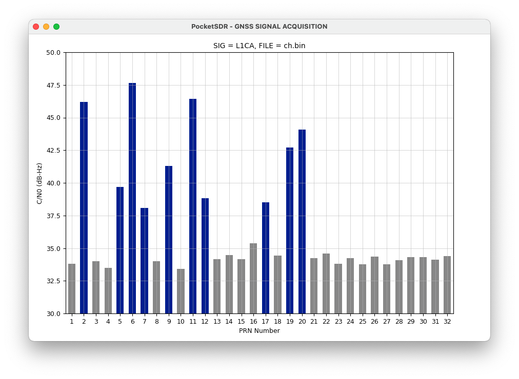
We were able to capture signals from multiple GPS satellites.
Next, in order to track the signal, we prepared another data ch1.bin that extended the observation time to about 30 seconds. Then, I noticed a problem that the histogram collapses once every few seconds to several tens of seconds. Professor Tomoji Takasu of Tokyo University of Marine Science and Technology uses Ubuntu 18.04 LTS because there are some signal omissions in observing signals with Ubuntu 20.04 LTS.
The OS will be replaced at the next opportunity, and Ubuntu 20.04 LTS will be used here. We try tracking the L1 C/A signal with a command ./pocket_trk.py -f 4 -prn 32 -sdr bladerf ch1.bin -p.
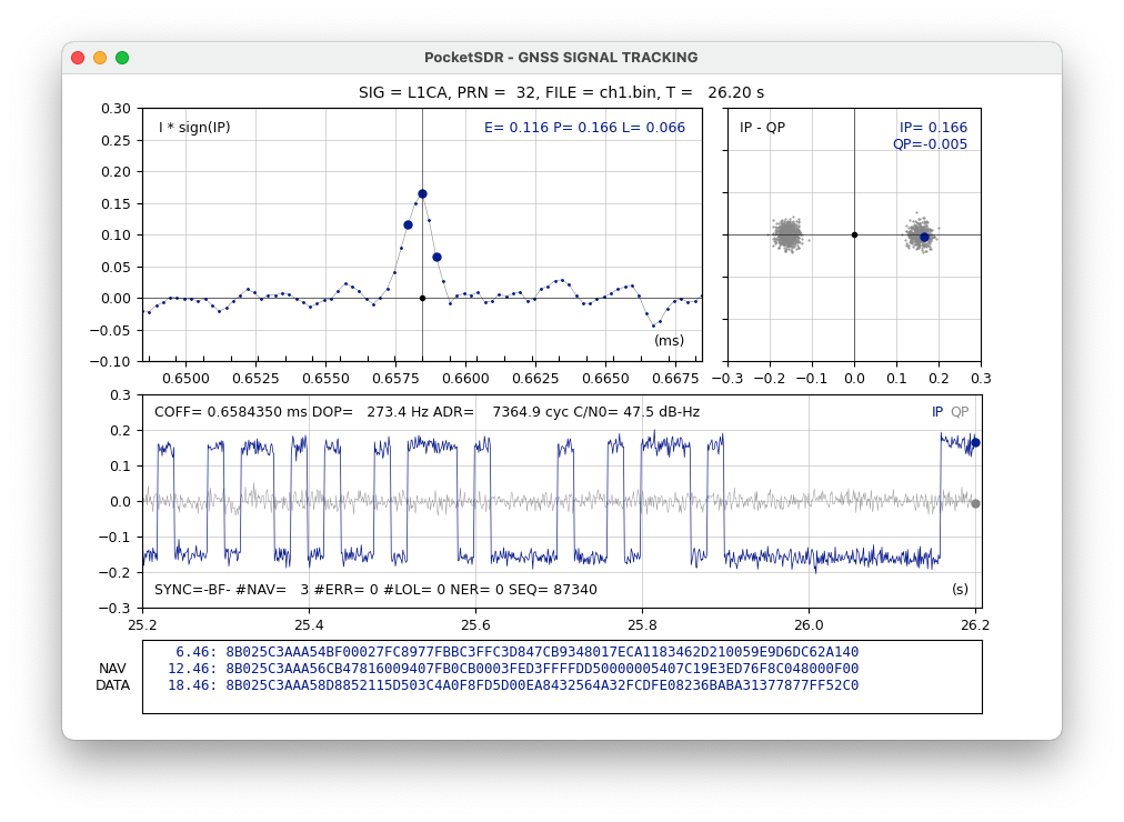
We can see the navigation data.
Next, the snapshot positioning is performed using this observation data ch.bin. This observation was made around 2022-03-04 14:31 UTC (Coordinated universal time). I got the navigation data 20220304o.nav required here by the same procedure as before.
$ ./pocket_snap.py -f 4 -nav 20220304o.nav ch.bin -ts 2022-03-04-14:31:00 -sdr bladerf
2022/03/04 14:31:00.000   -90.000000000    0.000000000 -6378137.000    5    0
TIME (s) = 4.938
Unfortunately, it’s a failure. Even if I fine-tuned the time and gave the rough coordinates of Hiroshima, I couldn’t get the coordinates.
L6D signal processing
The center frequency of L6-band signal of the quasi-zenith satellite, Michibiki, is 1.17645 GHz. Here, the sampling frequency is set to 12 MHz and the bandwidth is set to 10 MHz, respectively. We sampled and saved L6-band signal in the observation file l6.bin. The bladeRF command with bladeRF-cli -i is as follows.
set frequency rx 1.17645g
set bandwidth rx 10m
set samplerate rx 12m
set agc rx off
set gain rx 60
cal lms
cal dc rx
rx config format=bin n=100m file=l6.bin
rx start
rx wait
We find this power spectral density and histogram.
./pocket_psd.py -f 12 -IQ -h -sdr bladerf l6.bin
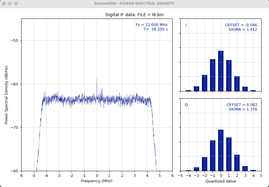
Next, we acquire this L6D signal.
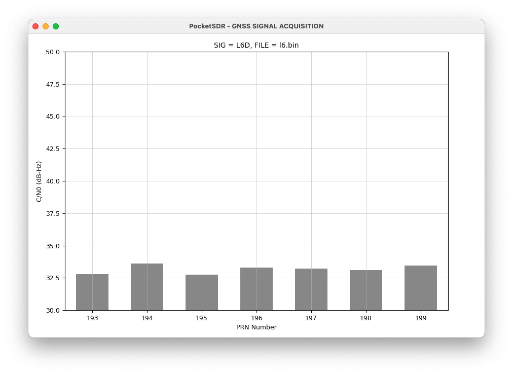
From this result, the L6D signal could not be found.
Conclusion
I used the general-purpose software defined radio bladeRF for GPS and quasi-zenith satellite as the signal observations. In the process, there were problems such as insufficient gain, insufficient utilization of signal capture bits, and demand for DC offset correction. Data loss may be due to the OS of the data collection computer.
I was able to capture and track the GPS L1 C/A signals and to acquire some of the navigation data, but I could not obtain the coordinates.
As additional experiments in the future, I am considering downgrading the OS of the data acquisition personal computer, adding LNA and adjusting the gain of RX VGA2 of bladeRF, supplying a stable clock by GPSDO (disciplined oscillator), and using other SDRs. However, I would like to use a PocketSDR hardware.
Related article(s):
- Awesome Pocket SDR (Effective use of configuration files) 30th April 2025
- Pocket SDR captured data 25th April 2025
- Awesome Pocket SDR (realtime positioning function) 13th October 2024
- Galileo E6B signal reception with Pocket SDR, a open source software-defined radio 27th January 2023
- Failure in reflow soldering 19th January 2023
- Pocket SDR hardware production (part 3) 30th September 2022
- Pocket SDR hardware production (part 2) 14th September 2022
- Pocket SDR hardware production (part 1) 4th September 2022
- Awesome PocketSDR (order of hardware parts) 9th April 2022
- I want to use bladeRF with PocketSDR AP, part 2 16th March 2022
- Awesome PocketSDR (snapshot positioning) 23rd February 2022
- Awesome PocketSDR (reducing processing time with FFTW) 19th February 2022
- Awesome PocketSDR (L6 band signal decode) 19th January 2022
- Awesome PocketSDR (pocket_trk) 28th December 2021
- Awesome PocketSDR(pocket_acq) 4th December 2021