Pocket SDR hardware production (part 2)
Introduction
The Pocket SDR hardware is roughly divided into a high frequency receiver and a USB interface. I thought that I was able to confirm the operation up to this USB interface part. To tell the truth, I may need to replace the EEPROM. I think it will be useful for firmware recovery, etc., so I will publish it.
Print circuit board cleaning
Last time, I flash the firmware of the USB interface FX2LP. Professor Takasu told me in his article on 2022-09-05 that CyUSB should be used instead of zadig as a driver for Windows. I thought it was already done because it was just a matter of replacing the PC driver.
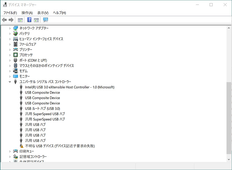
After a while, my Pocket SDR hardware connected to my computer had one of its white LEDs off. Furthermore, when I checked the device manager on the PC, this USB interface part was not recognized. I am getting the error “Device descriptor request failed”.
“I didn’t do anything and it broke.”
Actually, I was worried that my printed circuit board was dirty, even though the professors’ printed circuit boards were clean. I thought that the contaminants, the flux (soldering accelerator) contained in cream solder during reflow and the flux added during rework, had an adverse effect on insulation and component adhesion.
Therefore, I applied absolute ethanol to a toothbrush, gently brushed the terminals of all surface mount components, and then wiped them off with a Kimwipe, aiming to completely remove the flux (Reference: Aquchin Kobo’s YouTube How to Clean the Board Tips #06). Flux also adheres to the toothbrush, so occasionally wipe the dirt off the toothbrush with absolute ethanol and Kimwipe.
In the process, I found some floating parts that I hadn’t noticed before. One by one, I removed the parts from the board and reattached them. Until now, I thought that hardware recognition takes about 30 seconds. With this bug fix, the hardware was immediately recognized by the computer.
However, this hardware was still not recognized by my computer.
FX2LP firmware recovery
However, there was the solution in Professor Takasu’s article FX2LP firmware flashing.
If the EEPROM jumper is released, the EEPROM is separated from FX2LP (USB controller microcomputer), and it can be started alone. After FX2LP starts up, just short the EEPROM jumper to connect the EEPROM. Then, with the USB Control Center, we can load the basic firmware into the RAM area, modify a portion of the firmware, and transfer it to the EEPROM to initialize the EEPROM and write new firmware again. For the operation of the USB Control Center, please refer to Powering and firmware flashing.
The basic firmware to be loaded into the RAM area is included in the software bundled with Cypress’s (now Infineon) EZ-USB Development Kit (DVK) CY3684. After registering as an Infineon member on the web, download DOWNLOAD - CY3684Setup.exe of this Tools & Software and install it on your PC, and you can find the necessary Vend_Ax.hex.
The contents of the above article by Professor Takasu are as follows.
- Open the EEPROM jumper terminal and connect to the PC.
Cypress FX2LP No EEPROM Deviceappears in Universal Serial Bus Controllers in Device Manager. - Select
Program->FX2->RAMin the USB Control Center and selectVend_Ax.hex. We should see Programming succeeded in the lower left. - Short the EEPROM jumper terminals.
- Select
Cypress FX2LP No EEPROM Device->Configuration 1->Control endpoint (0x00)from the Data Transfer pane on the left side of the USB Control Center. 5.On theData Transfertab, change Req type fromStandardtoVendor, and Req code from0x00to0xA9. Other parts are left as default. Then, if you enterFFin the Data to send field, a garbled character will appear in Text to send, and Bytes to transfer will automatically change to 1. Finally press the Transfer Data button. If successful, you will see the words transfer completed.
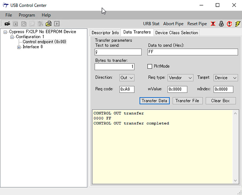
We can continue and flash the Pocket SDR’s firmware file (pocketsdr.iic). The operation itself is very easy. But I can’t seem to find a magic parameter like 0xA9 or this procedure. I would like to thank Prof. Takasu for sharing this procedure, and it was very helpful.
I may have corrupted the EEPROM
On my hardware, when I tried to flash the firmware in the Cypress USB Control Center, it said Programming failed. Until now, I was able to write the firmware to the EEPROM with this operation, but I’m sad that I can’t. As a test, in this write failure state, when I unplugged the hardware and plugged it back in, it became an “Unknown USB Device”.
Even if the Cypress USB Control Center displays a Programming failed message indicating that firmware flashing has failed, we can still clear the EEPROM by performing steps 4 and 5 above. We can also do it by trial and error without any jumper wire operations until the USB Control Center displays the words “Programming succeeded”.
When I tried to boot with the firmware that failed to write the firmware, it seems that only part of it works, so I’m guessing that part of the EEPROM is corrupted. I bought some of EEPROM, so I’m going to replace it. I’m sure that once you succeed in creating hardware, the creation success rate will skyrocket.
Conclusion
Pocket SDR v.0.8 uses CyUSB as the Windows USB driver. Removal of the flux on the printed circuit board until the component terminals look clean is the important procedure. To remove this flux, I used absolute ethanol, a toothbrush, and a Kimwipe. It’s also important to know the firmware recovery procedure in case we can’t boot.
It seems that I have broken the EEPROM, so I will try to replace it.
It feels like we’re three steps forward and two steps back to produce the Pocket SDR hardware, but I won’t give up. Please wait for the further report.
Related article(s):
- Awesome Pocket SDR (Effective use of configuration files) 30th April 2025
- Pocket SDR captured data 25th April 2025
- Awesome Pocket SDR (realtime positioning function) 13th October 2024
- Galileo E6B signal reception with Pocket SDR, a open source software-defined radio 27th January 2023
- Failure in reflow soldering 19th January 2023
- Pocket SDR hardware production (part 3) 30th September 2022
- Pocket SDR hardware production (part 1) 4th September 2022
- Awesome PocketSDR (order of hardware parts) 9th April 2022
- I want to use bladeRF with PocketSDR AP, part 2 16th March 2022
- I want to use bladeRF with PocketSDR AP 5th March 2022
- Awesome PocketSDR (snapshot positioning) 23rd February 2022
- Awesome PocketSDR (reducing processing time with FFTW) 19th February 2022
- Awesome PocketSDR (L6 band signal decode) 19th January 2022
- Awesome PocketSDR (pocket_trk) 28th December 2021
- Awesome PocketSDR(pocket_acq) 4th December 2021