Real-time CLAS positioning with u-blox ZED-F9P and Drogger VRSC
Introduction
In order to perform centimeter-order positioning by RTK (reltime kinematic), GNSS (global navigation satellite system) signal observation data observed at a reference station with known latitude, longitude, and ellipsoidal height is required. By using CLAS (centimeter level augmentation system) information broadcast from QZSS (quasi-zenith satellite system, petnamed as Michibiki), it is possible to create this virtual reference station (VRS) data, although it is limited to Japan. However, in order to use CLAS, in addition to RTK equipment such as a receiver, an antenna in the L6 frequency band, a CLAS decoder, and CLAS software, which are not yet common now, are required.
The BizStation’s Drogger VRSC (VRS by CLAS) released at the end of February 2021 is the hardware that packages these and creates the VRS observation data. In addition to this, if you have software such as GNSS receiver and RTKLIB that can output the carrier phase, you can perform RTK positioning without relying on a specific RTK reference station. VRSC is inexpensive at 600 USD with an antenna that can receive L6 signals.
This VRSC is supposed to be used in combination with the BizStation’s RWP receiver and DG-PRO1RW (S) receiver, but the information necessary for operation is disclosed in the technical guide. Here, based on that information, we used VRSC with u-blox ZED-F9P.
In fact, Professor Takasu of Tokyo University of Marine Science and Technology has already conducted an experiment with use of VRSC and ZED-F9P. Now that I’ve finally done it and I’ll summarize the details.
VRSC is intended to be used with the Bizstation’s receivers, so please refrain from inquiring about the contents of this article to BizStation. This is due to my technical interests and I do not recommend using the VRSC in combination with the ZED-F9P evaluaton kit.
Equipment setup
ZED-F9P settings
In addition to the VRSC main unit and u-blox ZED-F9P receiver, I prepare an external antenna (Beitian BT-200) and a splitter (Mini Circuits ZAPD-2DC-S+). In addition, we will need a Raspberry Pi 3, Windows 10 PC, and Android smartphone to check the operation.
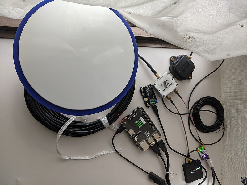
I have installed RTKLIB 2.4.3b34 on my Raspberry Pi and Windows 10 PC. Since the Raspberry Pi is used to connect to the NTRIP Caster via Wi-Fi to the VRSC, it is also connected to a wired network. I also have u-blox’s u-center software installed on my Windows 10 PC connected to a wired network.
I have installed Drogger VRSC on my Android smartphone. An Android smartphone is not required, but it is useful to have it for version upgrades and confirmations.
To use VRSC, satellite navigation data RXM-SFRBX (receiver manager - subframe data next generation) message and NAV-PVT (navigation - position, velocity, and timing) in ZED-F9P format is necessary to provide the VRSC. In addition, you need receiving the VRS observation data in RTCM format from VRSC while sending the these message to VRSC both in the NTRIP format. Also turn on the message RXM-RAWX (receiver manager - multi GNSS raw measurement data) to allow RTK positioning between this ZED-F9P and VRSC VRS. To do this, I connected the ZED-F9P to the Raspberry Pi and ran RTKLIB strstr with the following script. VRSC will create VRS observation data based on the coordinates contained in this NAV-PVT.
#!/bin/bash
#----------
DEV=ttyF9P
PORT=2001
STR2STR=/home/pi/exec/str2str
#----------
$STR2STR \
    -in  serial://$DEV:230400 \
    -out tcpsvr://:$PORT \
    -b 1 \
    > /dev/null 2>&1 &
-b is an option in str2str’s bi-directional mode, which allows you to give information on the output port 1 to the input port. Therefore, we can configure this ZED-F9P device via Raspberry Pi with u-center running on a Windows PC.
To output NAV-PVT raw data, open the Configuration View window from the View menu of u-center, and click MSG (Messages) and look for NAV-PVT in Message and check the USB port.
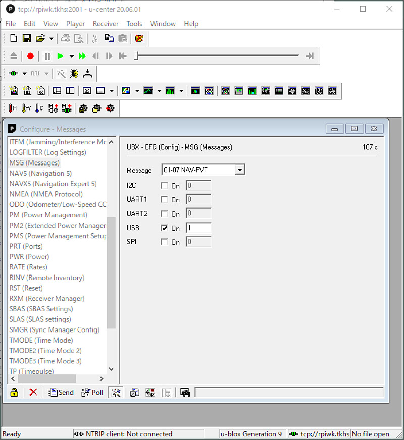
Immediately press the Send button at the bottom left. In u-center, we need pressing the Send button every time to reflect the settings.
Next, look for RXM-SFRBX in Message and check the USB port. Similarly, press the Send button at the bottom left.

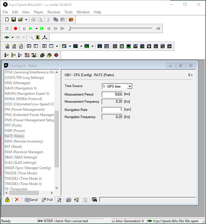
We also need extending the positioning interval to 5 seconds (at the rate 0.2 Hz). ZED-F9P is capable of positioning at the rate of 5 Hz, and it means wasting the capability, but it can’t be helped. Find RATE (Rates) in the left menu of u-center, enter 5000 in Measurement Period [ms], and press the Send button in the lower left.
Finally, turn off unnecessary messages to reduce the load on the VRSC. Since CLAS augments the signals of GPS, QZSS (Michibiki), and Galileo, turn off satellite systems other than these satellite systems with GNSS and press the Send button. Also, to turn off NMEA-0183 messages, uncheck the MSG F-xx message output checkbox and press the Send button.
After completing these settings, select the Save current configuration radio button in the left menu CFG (Configuration) and press the Send button in the lower left. Now exit u-center.
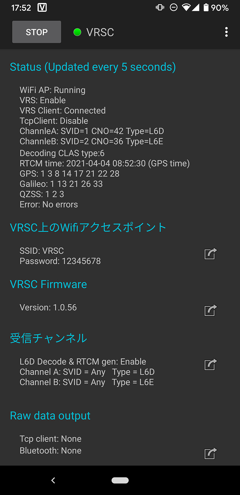
VRSC status check
WWi-Fi SSID VRSC will appear when you power the VRSC with the USB cable. The initial password is 12345678. I powered the VRSC from the Raspberry Pi’s USB port, because I was hoping that a serial port would appear on the Raspberry Pi and the CLAS augmentation information could be retrieved via the USB serial port, but I couldn’t do that. When you search for a Bluetooth device with Andoid, VRSC will appear, so pair it, change the Wi-Fi password from the application Drogger VRSC, output raw data of CLAS and MADOCA, and update the firmware. VRSC seems to be able to receive and decode CLAS and MADOCA at the same time, unlike Allystar’s HD9310 Option C.
Connection from Raspberry Pi to VRSC
To connect the Raspberry Pi to the VRSC Wi-Fi, I set /etc/wpa_supplicant/wpa_supplicant.conf as follows:
country=JP
ctrl_interface=DIR=/var/run/wpa_supplicant GROUP=netdev
update_config=1

network={
    ssid="VRSC"
    psk="12345678"
}
Then restart the Raspberry Pi to enable the Wi-Fi connection. Make sure that the wlan0 device is assigned the address 192.168.4.2 with ip li command. The IP address of VRSC will be 192.168.4.1. I found in the log of Raspberry Pi that VRSC used the ESP32 microcomputer of Espressif System.
Utilize RTKLIB str2str on Raspberry Pi to receive RTCM messages while injecting NAV-PVT and RXM-SFRBX into VRSC.
#!/bin/bash
#------------------------------------------
IP=192.168.4.1
RPORT=2001
LPORT=9999
STR2STR=/home/pi/exec/str2str
#------------------------------------------
$STR2STR \
    -in  ntrip://$IP/VRSC \
    -out tcpsvr://:$LPORT \
    -b 1 \
    > /dev/null 2>&1 &

sleep 2

$STR2STR \
    -in  tcpcli://localhost:$RPORT \
    -out tcpcli://localhost:$LPORT \
    > /dev/null 2>&1 &

# EOF
After all, I was running three str2str processes in the background. We can check and modify the settings of u-blox ZED-F9P on TCP port 2001, while RTCM format VRS observation message is output to TCP port 9999. The data flow is as follows.
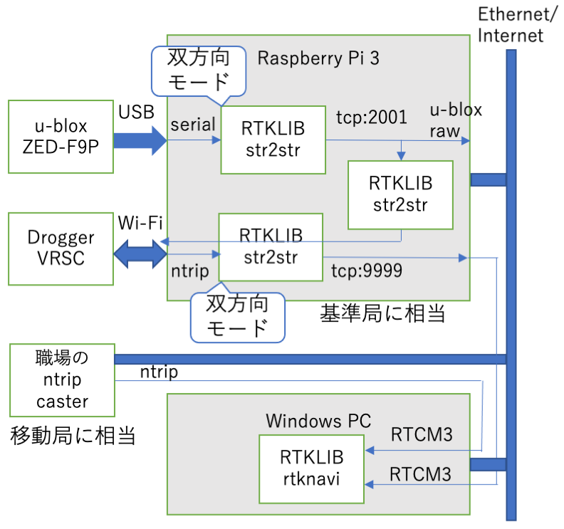
Consider this VRS observation message as a reference station message and estimate an RTK reference station coordinates.
RTK positioning with RTKNAVI on a Windows PC
I used STRSVR of RTKLIB to confirm that RTCM message was output from VRSC.
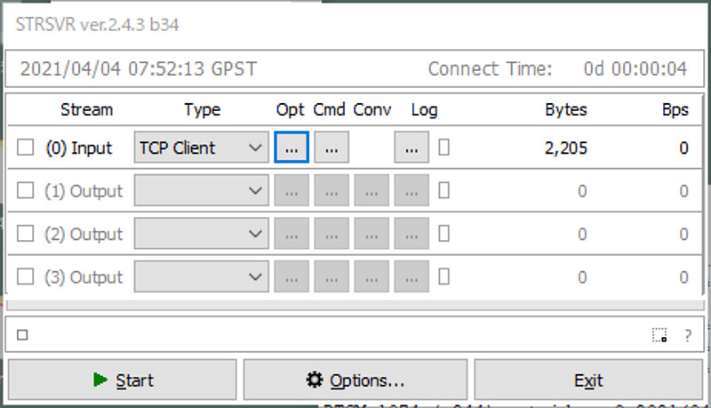
Select TCP Client and (0) Input and set the IP address and port number (9999 in this case) of Raspberry Pi in Opt. tab. Then we would see the RTCM messages by pressing Start, pressing the square button at the top, and selecting RTCM 3 as the message to decode.
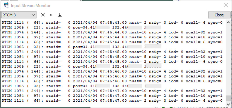
In the figure, RTCM 1005 (coordinate), RTCM 1074 GPS MSM4 (observation data)、RTCM 1094 Galileo MSM4, and RTCM 1114 QZSS MSM4 were observed.
Next, RTK positioning is performed using this VRS. Launch RTKNAVI in RTKLIB and press the I button at the top of the window to set the input stream.
Select NTRIP Client as the type for Input Stream (1) Rover, and select the device information you want to observe in Opt tab (Address ntrip.rnav.info.hiroshima-cu.ac.jp, Port 80, and Mouont Point OEM7) has been set. On the other hand, as (2) Base Station, I entered TCP Client in Type and the IP address and port number of Raspberry Pi in Opt. tab. Here, I selected the RTK reference station of Hiroshima City University as the observation point, but it is of course possible to use your observation equipment or this ZED-F9P.
Setting 1 of Option was set as follows.
| item | parameter |
|---|---|
| Positioning Mode | Kinematic |
| Frequencies | L1+L2 |
| Elevation Mask | 20 |
| Ionosphere Correction | Broadcast |
| Troposhere Correction | Saastamoinen |
| Satellite Ephemeris | Broadcast |
| Satellite | GPS, Galileo, QZSS |
This is a setting that uses the Klobuchar model based on the broadcast signal (broadcast) instead of the dual frequency observation result (Iono-Free LC) as ionospheric correction. This is because not all GPS satellites broadcast more than two frequencies, and Iono-Free LC wastes the positioning results of such satellites. Other settings are the default values for RTKNAVI. I have selected all available satellite systems, but sometimes it is easier to fix with just GPS and QZSS, or just GPS.
Setting 2 is as follows.
| item | parameter |
|---|---|
| Integer Ambiguity Resolution | Instanteneous |
| Min Ratio to Fix Ambiguity | 2.0 |
This is a setting that solves the integer uncertainty for each positioning epoch and changes the ratio test to be determined as Fix from the usual 3 to 2. This is to make it converge quickly. The result is as follows.
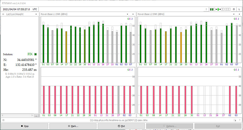
The baseline length from the observation station to this virtual reference station is approximately 4 km. CLAS with current type 12 messages produces VRS observations for up to 17 satellites. Here, 16 to 17 VRS observation data were created.
Since it is a virtually created reference station, its signal strength is meaningless, but it is interesting that it is not possible for a general RTK to display that all satellite signal strengths are the same. On the other hand, the ratio value fluctuates between 2 and 40. In a normal RTK, the ratio value often reaches the maximum value of 999 after operating for a while, but this may be the limit because it is a reference station signal created with information of only 2 kbit/s.
The update rate for VRS observations was 1 Hz.
By default, VRSC updates the reference station coordinates every time the coordinates of ZED-F9P that supplies NAV-PVT move 1 km, but it may be possible to change this distance with the Android application.
When RTCM message from VRSC is not obtained
If all three LEDs on the VRSC are lit, it is likely that the RTCM message is being output.
If the green LED in the center is blinking, it seems that the VRSC’s Wi-Fi connection is not established. Check the Wi-Fi settings on your Raspberry Pi.
If the orange LED on the right is blinking, you have received the L6D signal but have not created a VRS. Connect to TCP port 2001 of Raspberry Pi at u-center, select MSG (Message) from the View Message window in View, and please make sure that NAV-PVT and RXM-SFRBX messages are output. Also, make sure that the Measurement Period of the RATE in the Configuration View window is 5000 ms.
VRSC doesn’t seem to create VRS for the case that the reception condition is not good. Using good antenna and locating it in good environment are important. I have tried installing a multi-frequency antenna outdoors, but the RTCM output often stops, probably because the installation environment is not good.
If you are observing for a long time, the orange LED may turn on and an RTCM message may be output. Also, after resetting the VRSC, the RTCM output could be restored.