GNSS receiver bynav C1-FS
Introduction
With a budget of less than 1,000 USD including the development board (EVK: evaluation kit), I wanted to try a new GNSS (global navigation satellite system) receiver.
As a candidate, I narrowed down to unicore UB4B0 and bynav C1-FS, and downloaded and examined their online manual. The unicore UB4B0 is equipped with a Nebulas II chip that can receive 432 channels simultaneously. It can handle satellite signals of GPS L1CA/L2C/L2P(Y)/L5, GLO L1/L2, GAL E1/E5a/E5b, QZS L1CA/L2/L5, and BDS B1I/B2I/B3I/B1C/B2a, and the maximum measurement rate is 20 Hz. On the other hand, bynav C1-FS is equipped with Alita chip, and it can process satellite signals of GPS L1CA/L1C/L2C/L2P(Y)/L5, GLO L1/L2, GAL E1/E5a/E5b, QZS L1CA/L1C/L2C/L5, BDS B1I/B2I/B3I/B1C/B2a/B2b, IRN L5, and SBAS L1CA. The maximum rate is 10 Hz, but the number of simultaneous reception channels is not disclosed. Both have a wired Ethernet interface, and the antenna connector format on the board is MMCX.
I thought both EVKs were good, but I chose C1-FS because Professor Takasu of Tokyo University of Marine Science and Technology is using bynav C1-F8 and A1-3L and the number of compatible signals is large.
Purchase of bynav C1-FS
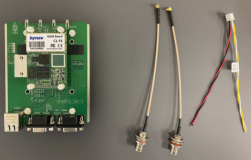
The power supply is direct current from 9 volts to 24 volts. I connected the plus to both the red and black lines and the minus to both the yellow and white lines. It takes courage to supply positive power to the black wire, but I confirmed with a tester that there is continuity between the red wire terminal and the black wire terminal on the board.
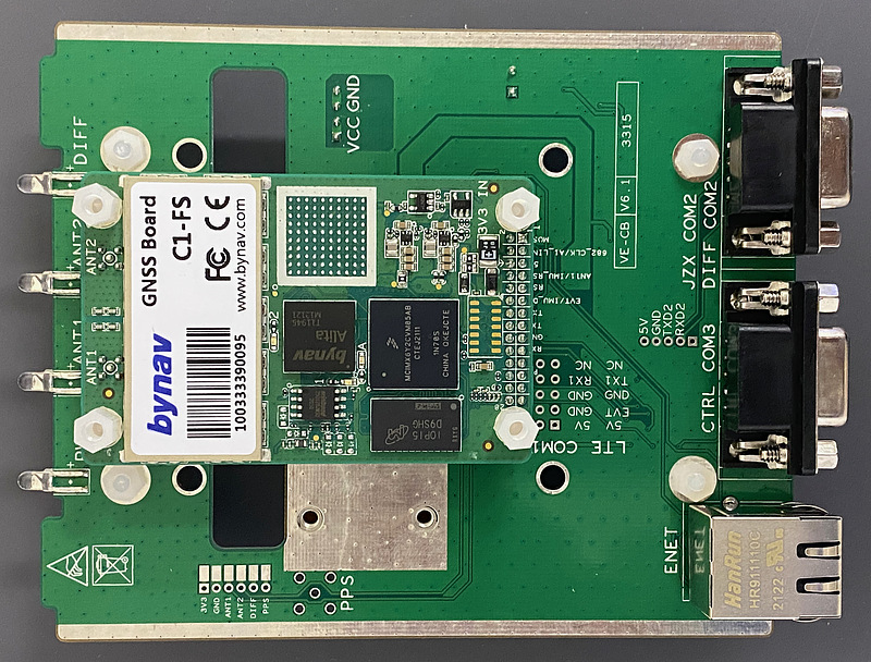
This is a picture of the EVK surface. The module board is the size of a business card, but the EVK is slightly larger. You can see the baseband chip Alita in the center.
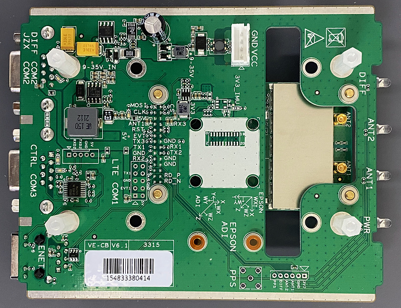
On the back of the EVK, we can see the two MMCX antenna terminals on the module. The C1-FS is a single antenna model, but it has two antenna terminals. It seems to be common with the dual antenna type C1-FD. I expected a little to be able to observe dual antennas.
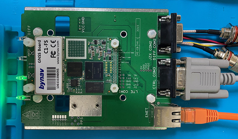
When power was supplied, the power LED PWR and antenna 1 LED ANT1 were lit, antenna 2 LEDANT2 was blinking, and DIFF was off.
Configuration
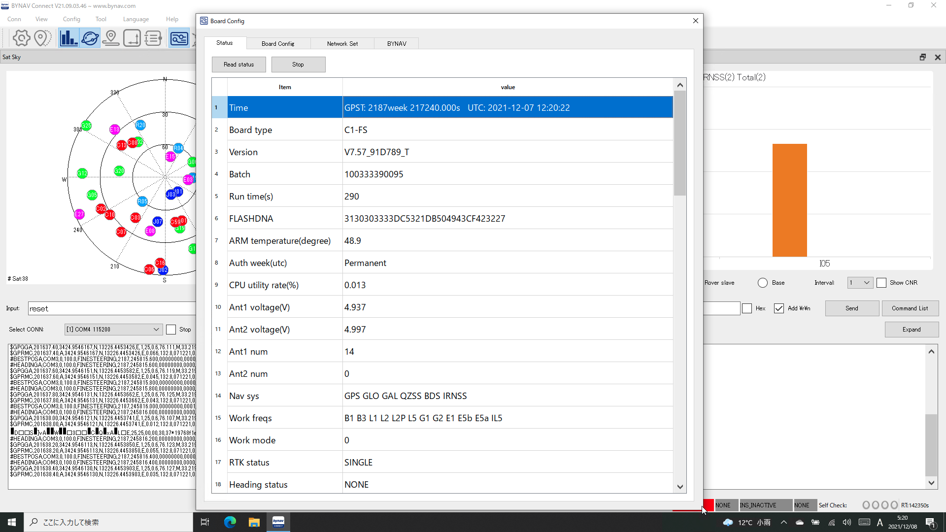
I installed the support software BYCONNECT on your Windows 10 PC, connected the EVK COM3 port (central DSUB 9 connector) to your PC. Then I could read the board information from this software.
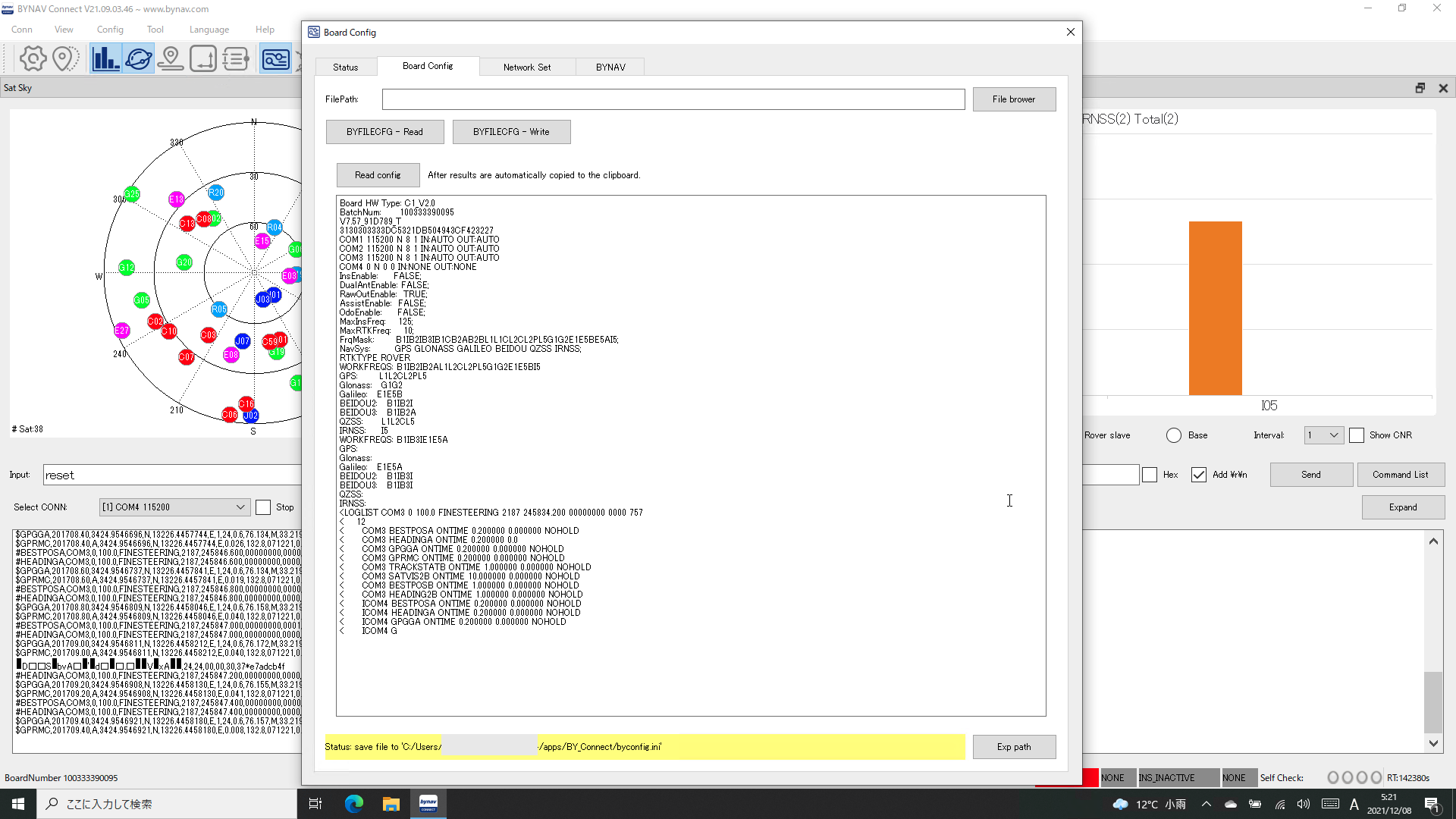
Board HW Type: C1_V2.0
BatchNum:      100333390095
V7.57_91D789_T
3130303333DC5321DB504943CF423227
COM1 115200 N 8 1 IN:AUTO OUT:AUTO
COM2 115200 N 8 1 IN:AUTO OUT:AUTO
COM3 115200 N 8 1 IN:AUTO OUT:AUTO
COM4 0 N 0 0 IN:NONE OUT:NONE
ICOM1 TCP :1111 IN:AUTO OUT:AUTO
ICOM2 TCP :2222 IN:AUTO OUT:AUTO
ICOM3 TCP :3333 IN:AUTO OUT:AUTO
AuthStr:       37BE7CBBD978244E9A18E94F3A35B9BF;
AuthMode:      C1-FS;
Authorization: Permanent Licence;
InsEnable:     FALSE;
DualAntEnable: FALSE;
RawOutEnable:  TRUE;
AssistEnable:  FALSE;
OdoEnable:     FALSE;
MaxInsFreq:    125;
MaxRTKFreq:    10;
FrqMask:       B1IB2IB3IB1CB2AB2BL1L1CL2CL2PL5G1G2E1E5BE5AI5;
NavSys:        GPS GLONASS GALILEO BEIDOU QZSS IRNSS;
RTKTYPE ROVER
WORKFREQS: B1IB2IB2AL1L2CL2PL5G1G2E1E5BI5
GPS:       L1L2CL2PL5
Glonass:   G1G2
Galileo:   E1E5B
BEIDOU2:   B1IB2I
BEIDOU3:   B1IB2A
QZSS:      L1L2CL5
IRNSS:     I5
WORKFREQS: B1IB3IE1E5A
GPS:
Glonass:
Galileo:   E1E5A
BEIDOU2:   B1IB3I
BEIDOU3:   B1IB
QZSS:
IRNSS:
<LOGLIST COM3 0 100.0 FINESTE
<    11
<      COM3 BESTPOSA ONTIME 0.200000 0.000000 NOHOLD
<      COM3 HEADINGA ONTIME 0.200000 0.000000 NOHOLD
<      COM3 GPGGA ONTIME 0.200000 0.000000 NOHOLD
<      COM3 GPRMC ONTIME 0.200000 0.000000 NOHOLD
<      COM3 BESTPOSB ONTIME 1.000000 0.000000 NOHOLD
<      COM3 HEADING2B ONTIME 1.000000 0.000000 NOHOLD
<      COM3 TRACKSTATB ONTIME 1.000000 0.000000 NOHOLD
<      ICOM4 BESTPOSA ONTIME 0.200000 0.000000 NOHOLD
<      ICOM4 HEADINGA ONTIME 0.2
<      ICOM4 GPGGA ONTIME 0.200000 0.000000 NOHOLD
<      ICOM4 GPRMC ONTIME 0.200000 0.000000 NOHOLD
The firmware version was 7.57, which was the latest version. The support software screen displays many NMEA messages, as well as directional and IMU information for dual antennas. I tried connecting two separate antennas to the two antenna terminals, but the directional output and IMU output remained zero.
First, I set the Ethernet to automatically acquire the address by DHCP.
ipconfig etha dhcp
<OK
[USB1]
Now I can control C1-FS from my usual Macbook Air terminal via Ethernet.
nc -c [IP address] 1111
log version
log version
$BDVER,V7.57_91D789_T,19060377,21031038,21012830,21012850,21011325,20101504,20073004,21012209*04
<OK
[ICOM1]
In the following, the prompts <OK and [ICOM1] messages will be omitted. This C1-FS doesn’t have an IMU, so I’ve hidden the messages associated with it.
unlog com3 headinga
unlog com3 corrimudatab
unlog icom1 insconfig
unlog icom1 inscalstatusa
unlog icom4 headinga
There are a total of 4 ICOM ports that can be input/output to and from this receiver via Ethernet. Here, I decided to use the ICOM1 port for normal control, the ICOM2 port for raw data output, the ICOM3 port for RTCM3 output, and ICOM4 for the default status check. The ICOM1 port number is 1111, that of ICOM2 is 2222, that of ICOM3 is 3333, and that of ICOM4 is 4444. First, I set the ICOM2 port to output the raw data.
log icom2 rangecmpb ontime 1
log icom2 bdsephemerisb onchanged
log icom2 galephemerisb onchanged
log icom2 gpsephemb onchanged
log icom2 gloephemerisb onchanged
log icom2 qzssephemerisb onchanged
log icom2 ionutcb onchanged
The b at the end of the command represents the binary data (raw data).
The manual did not define the NavIC ephemeris output format. By analogy with other systems, I tried navicephemerisb and navicephemb, but I get an Invalid Message Field error and it seems unlikely that I can output the NavIC ephemeris. On the other hand, the NavIC pseudo-distance can be output with rangecmpb, and its format is defined.
Next, I assigned the ICOM3 port as the RTCM message output.
log icom3 rtcm1077 ontime 1
log icom3 rtcm1087 ontime 1
log icom3 rtcm1097 ontime 1
log icom3 rtcm1107 ontime 1
log icom3 rtcm1127 ontime 1
log icom3 rtcm1137 ontime 1
log icom3 rtcm1019 onchanged
log icom3 rtcm1020 onchanged
log icom3 rtcm1042 onchanged
log icom3 rtcm1044 onchanged
log icom3 rtcm1046 onchanged
log icom3 rtcm1048 onchanged
log icom3 rtcm1230 onchanged
log icom3 rtcm1033 ontime 5
log icom3 rtcm1005 ontime 1
As Professor Takasu pointed out, the Galileo F/NAV RTCM3 message was not in the manual, and I could not output it.
log icom3 rtcm1045 onchanged
<ERROR:Invalid Message Field
Then check with log loglist that the output is set correctly.
log loglist
<LOGLIST ICOM1 0 100.0 FINESTEERING 2187 573429.800 00000000 0000 757
<    28
<      COM3 BESTPOSA ONTIME 0.200000 0.000000 NOHOLD
<      COM3 GPGGA ONTIME 0.200000 0.000000 NOHOLD
<      COM3 GPRMC ONTIME 0.200000 0.000000 NOHOLD
<      ICOM2 RANGECMPB ONTIME 1.000000 0.000000 NOHOLD
<      ICOM2 BDSEPHEMERISB ONCHANGED 0.000000 0.000000 NOHOLD
<      ICOM2 GALEPHEMERISB ONCHANGED 0.000000 0.000000 NOHOLD
<      ICOM2 GPSEPHEMB ONCHANGED 0.000000 0.000000 NOHOLD
<      ICOM2 GLOEPHEMERISB ONCHANGED 0.000000 0.000000 NOHOLD
<      ICOM2 QZSSEPHEMERISB ONCHANGED 0.000000 0.000000 NOHOLD
<      ICOM2 IONUTCB ONCHANGED 0.000000 0.000000 NOHOLD
<      ICOM3 RTCM1077 ONTIME 1.000000 0.000000 NOHOLD
<      ICOM3 RTCM1087 ONTIME 1.000000 0.000000 NOHOLD
<      ICOM3 RTCM1097 ONTIME 1.000000 0.000000 NOHOLD
<      ICOM3 RTCM1107 ONTIME 1.000000 0.000000 NOHOLD
<      ICOM3 RTCM1127 ONTIME 1.000000 0.000000 NOHOLD
<      ICOM3 RTCM1137 ONTIME 1.000000 0.000000 NOHOLD
<      ICOM3 RTCM1019 ONCHANGED 0.000000 0.000000 NOHOLD
<      ICOM3 RTCM1020 ONCHANGED 0.000000 0.000000 NOHOLD
<      ICOM3 RTCM1042 ONCHANGED 0.000000 0.000000 NOHOLD
<      ICOM3 RTCM1044 ONCHANGED 0.000000 0.000000 NOHOLD
<      ICOM3 RTCM1046 ONCHANGED 0.000000 0.000000 NOHOLD
<      ICOM3 RTCM1048 ONCHANGED 0.000000 0.000000 NOHOLD
<      ICOM3 RTCM1230 ONCHANGED 0.000000 0.000000 NOHOLD
<      ICOM3 RTCM1033 ONTIME 5.000000 0.000000 NOHOLD
<      ICOM3 RTCM1005 ONTIME 1.000000 0.000000 NOHOLD
<      ICOM4 BESTPOSA ONTIME 0.200000 0.000000 NOHOLD
<      ICOM4 GPGGA ONTIME 0.200000 0.000000 NOHOLD
<      ICOM4 GPRMC ONTIME 0.200000 0.000000 NOHOLD
<OK
[ICOM1]
Finally I saved these settings.
saveconfig
The ICOM connection can be terminated with CTRL + D.
The C1-FS has some rough edges, such as no NavIC Ephemeris output or Galileo F/NAV RTCM3 message output, but I’m looking forward to future firmware updates.
Experiment
After that, I observed the ICOM2 output and it seemed that the raw data was being output (nc -c [IP address] 2222). However, no message appeared in the ICOM3 output.
The bynav raw data is compatible with NovAtel raw data to some extent, so I tried to interpret this raw data with the receiver setting OEM7 of RTKLIB 2.4.3b34 RTKNAVI. I set the RTK and set RTCM3 of my NovAtel OEM729 as the reference station data (host is ntrip.physrnav.info.hiroshima-cu.ac.jp, port number is 80, mount point is OEM7).
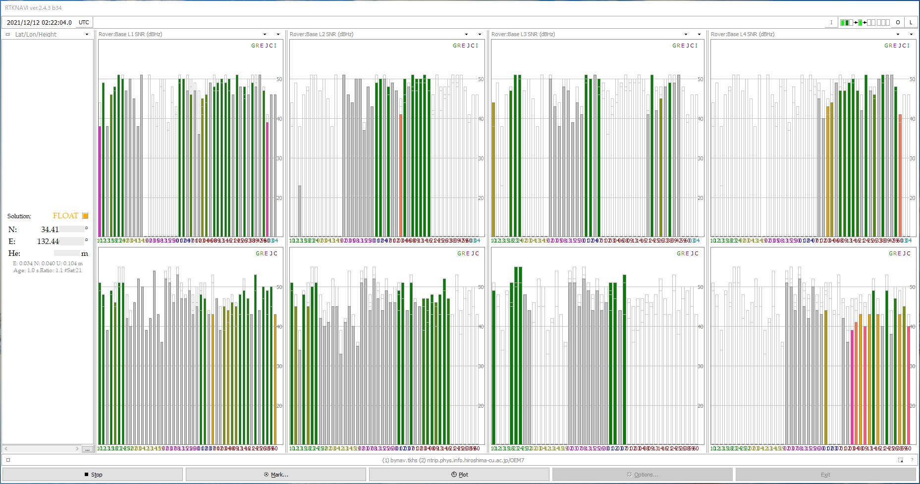
The upper row shows the raw data of this bynav C1-FS, and the lower row shows the raw data of NovAtel OEM729 at work converted to RTCM3 data by RTKLIB str2str. Although it is a simple evaluation, the operation was confirmed. I will take a closer look from now on.
The reason why RTCM3 output could not be performed on the ICOM3 port of C1-FS may be because the mode of this port was not set. I will proceed with the experiment.