Pocket SDR hardware production (part 1)
Introduction
I am making hardware that receives signals of navigation satellites such as GPS. Pocket SDR is an outstanding open-source software defined radio published on GitHub by Professor Tomoji Takasu of Tokyo University of Marine Science and Technology. It consists of a hardware part and a software part. This article is about that hardware part.
To tell the truth, I haven’t been able to receive signals yet with the hardware I made, but I think I’m one step closer, so I’ll summarize the work I’ve done so far.
Actually, there are parts that I do not know the correct way, and there may be an error in the following description. However, I will publish my method because I think it will be useful for those who want to create hardware for Pocket SDR. Please take responsibility for your actions. This article is a little long, but please bear with me.
Preparation
While preparing the reflow oven and procuring parts necessary for hardware creation, I set up the Windows PC and confirmed the design documents.
In addition, instead of the memory IC Microchip AT24C128C-XHM-T that was not available, I purchased ROHM BR24S128FVT-W (Reference: Compatible with 128Kbits EEPROM AT24C128C-XHM-T in Professor Takasu’s article). Also, although it was also difficult to purchase board-mounted SMA connectors online (why?), I was able to purchase them easily at Akizuki Denshi.
For Windows PCs, do the following:
Installation of MSYS2 (Reference: Construction of host AP development environment for Pocket SDR in Professor Takasu’s article)
Required software installation in MSYS2 terminal
pacman -S base-devel git gcc vim mingw-w64-x86_64-libusb mingw-w64-x86_64-fftwDownload Pocket SDR in MSYS2 terminal
git clone https://github.com/tomojitakasu/PocketSDR pocketsdrDownload FX2LP USB Driver CyUSB
Download the generic USB driver zadigFrom Pocket SDR v.0.8, CyUSB is used as a driver for Windows and this step is unnecessary (reference: the article on 2022-09-05 by Prof. Takasu)update on 2022-04-14
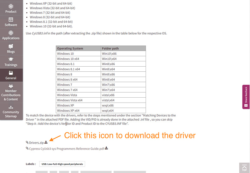
Since the link in the CyUSB download in step 4 is difficult to find out, please refer to the following.
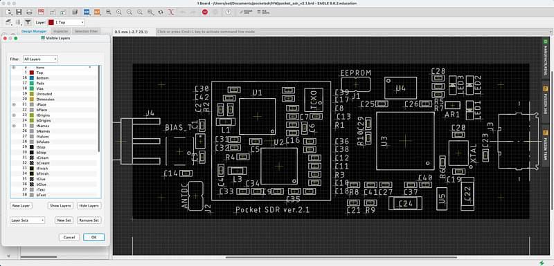
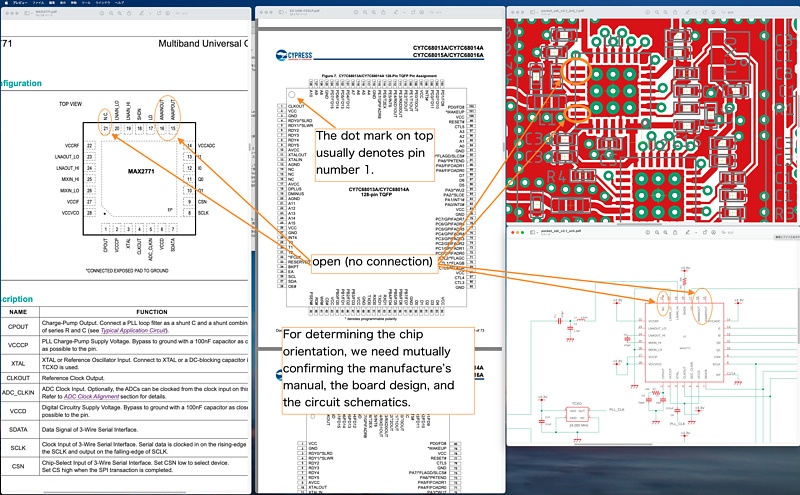
Next, print the board drawing and check the pins of the polar parts. I printed pocketsdr-production-first-report.png created by selecting layers with Autodesk EAGLE and reversing black and white.
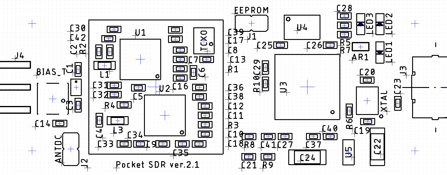
Write the part number such as U1 U2, AR1 on the bag of purchased parts.
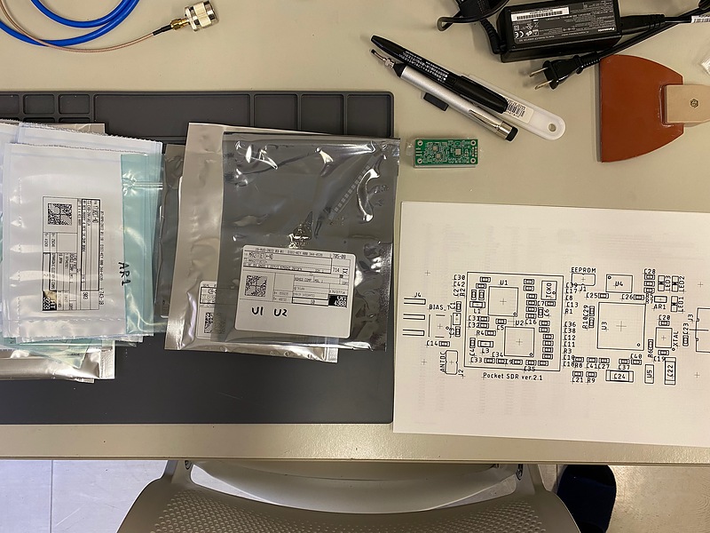
Also check the orientation of the MAX2771, LEDs, etc. A dot mark printed on the surface of the component often indicates pin 1, but the component installation direction is determined by cross-checking the specifications, board drawing, and circuit diagram. I downloaded the material to my regular computer and displayed it on my 4K monitor as needed.
PCB production
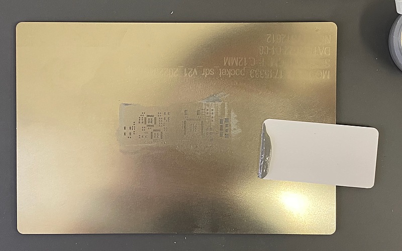
To solder components to the printed circuit board (PCB), align the holes in the metal mask (stencil) with the terminal surface (land) of the PCB and apply cream solder. I used extra PCBs so that there is no gap between the stencil and the target PCB.
After that, mix the cream solder with a spatula, paste it to the stencil, and I pour solder evenly into the holes of the stencil with a spatula (squeezer).
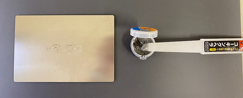
This plastic squeegee MINISQUEEGE-1 is relatively expensive at about 3 USD, and the product I received has burrs and looks a bit rough, but for some reason I can apply cream solder beautifully. This looks like a simple plastic plate, but it may actually be a know-how product.
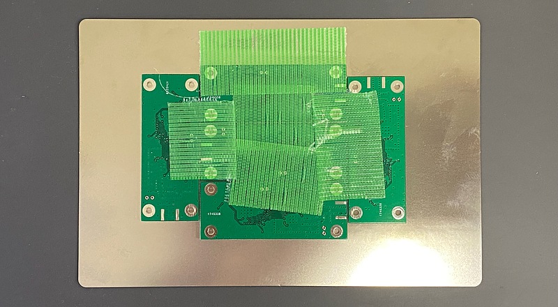
Below is a photo of the board with cream solder applied. In hindsight, it was a lot of solder. Cream solder should have been chilled in the refrigerator until just before use (reference: article Implementation tips for self-made reflow by Professor Takasu).
After that, the components are placed on the PCB. ICs, polar parts, non-polar parts, and large parts (bias ties and USB connectors) are placed on the PCB in that order. Parts delivered from Digi-Key are bagged by part item. When opening the bag with scissors, say the part number such as C35 before arranging the parts to prevent misplacement.
Large parts such as MAX2771 and FX2LP are placed on the board using a suction dropper (I used HAKKO 393), and small parts such as resistors and capacitors are placed on the board using tweezers.
Dirt from the bag of parts or the board may adhere to the tweezers, and the parts may remain attached even after the tweezers are opened. I wiped the tips of the tweezers with absolute ethanol and Kimwipes after each part or every two parts. Also, if your hands feel dirty, wash them with soap.
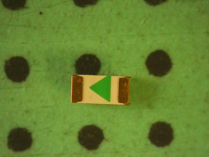
A microscope with a TFT monitor (I used GVDA GD7010) was used to mark the polar parts. This microscope was also very useful for later rework (correction of soldering of PCB). The LED has an arrow pointing from the anode to the cathode, so match the direction with the printed mark on the board.
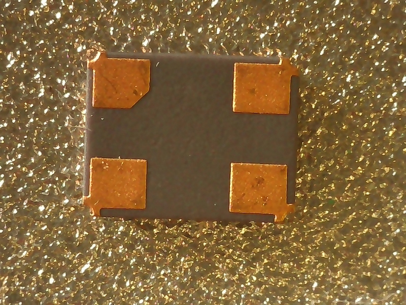
The crystal oscillator (XTAL) does not have any particular markings, but there is a notch on the back side. This notch represents pin 1, so when the part number is oriented so that the part number can be read, the lower left pad should be aligned with the circle mark on the board.
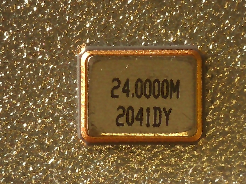
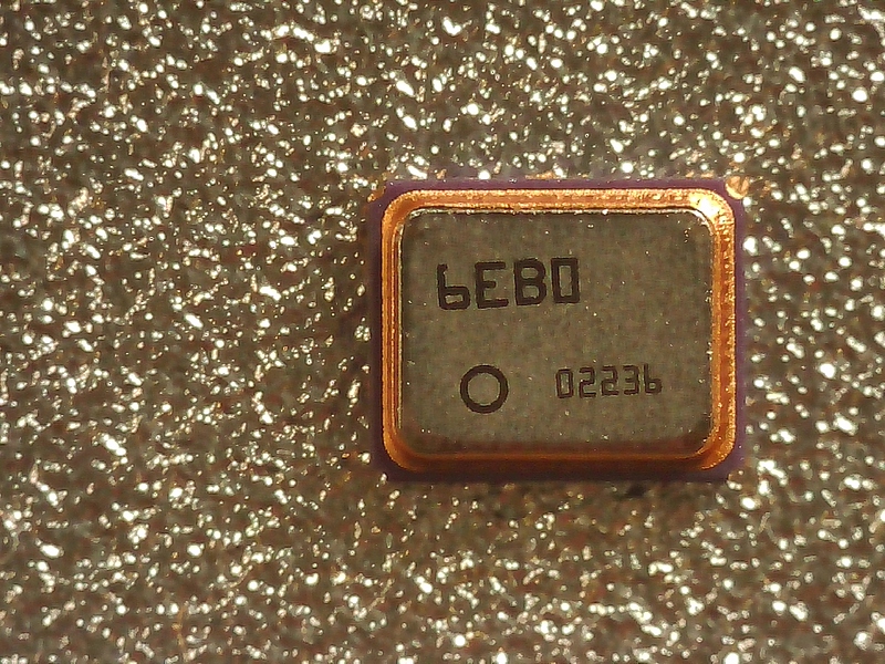
The temperature compensated crystal oscillator (TCXO) had a circle mark representing pin 1.
The component bias tee (BIAS-T) that powers the antenna also has polarity. This had a circle mark on the top. Once all the parts are on, it’s time to reflow.
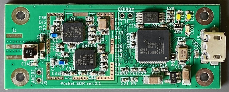
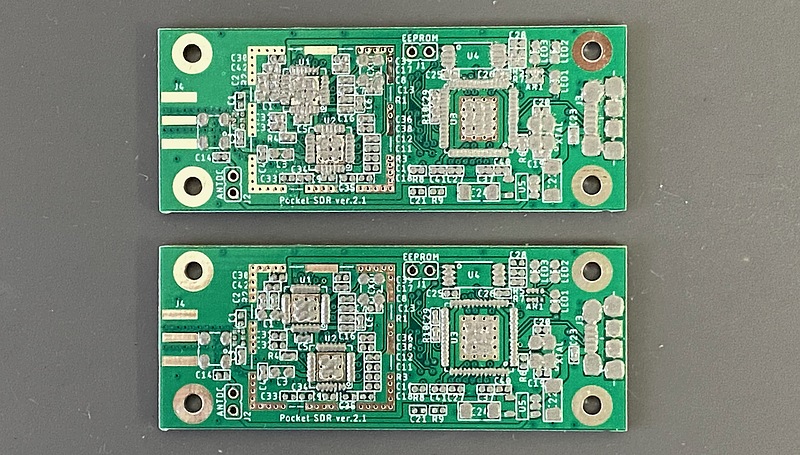
This time, I made two same equipments at the same time. It is recommended to make two sets at the same time in order to check the position of parts and improve work efficiency. Following picture is PCB after reflow. This indicate parts what I believe to be true as it helps verify the placement of polar parts.
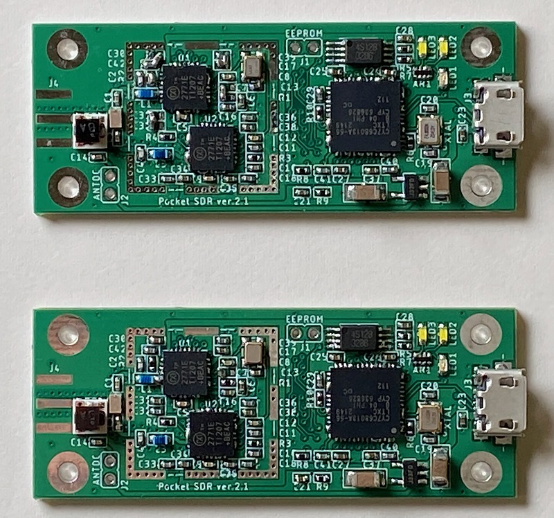
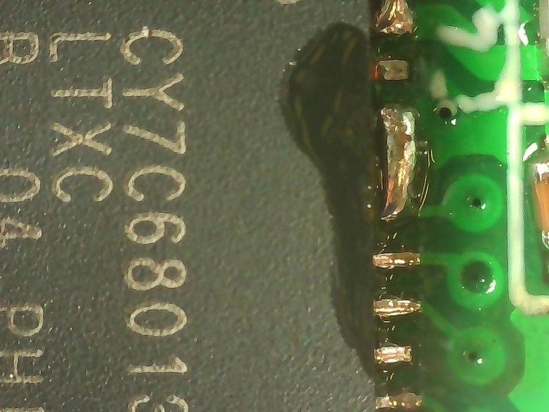
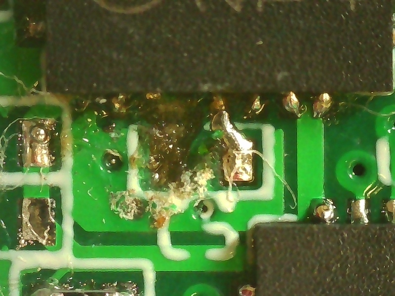
As you can see, the FX2LP and MAX2771 have solder bridges on the terminal pins. I am full of sad thoughts.
Rework and installation of remaining parts
However, when I tried (3) of Professor Takasu’s article self-made reflow mounting tips,
Most of all solder bridges can be fixed by applying flux and a little large-capacity soldering iron,
I could fix the solder bridges!
I cleaned the tip of the soldering iron, applied flux, and slowly moved the soldering iron from the back of the pin to the front, and the solder bridge disappeared. Then pick up a Kimwipe soaked in absolute ethanol and use it to remove the flux and check under the microscope that there are no more bridges there. Do this fluxing, soldering iron fix, deflux, check step for all bridged terminals.
I use AS ONE’s Hand Wrap 200 to soak Kimwipes in absolute ethanol. This hand wrap is famous for its hard lid, but it can be made easier to use by shaving off the claws with a utility knife. Even if Kimwipe is used, countermeasures against the fact that fibers still remain are issues to be examined in the future.
As a soldering iron, I newly purchased PX-280) of Taiyo Denki Sangyo (goot). The temperature rises very quickly before you start using it, and the vibration sensor on the main unit automatically lowers the temperature when not in use, which is very convenient (Reference: Ichiken’s YouTube article.
For chip parts that are bent and attached to the board, remove them and attach them again (Reference: Aquchin Kobo’s YouTube article: How to remove and replace chip resistors). These are 1005 size (1mm and 0.5mm rectangles), so they are smaller than a grain of rice and very difficult to fix. Sadly, one of the two printed circuit boards I made had a blunder of peeling off the land (copper foil surface) in a hurry to correct the mounting of the chip capacitor. I will reuse the hard-to-purchase MAX2771, FX2LP, TCXO, and memory ICs.
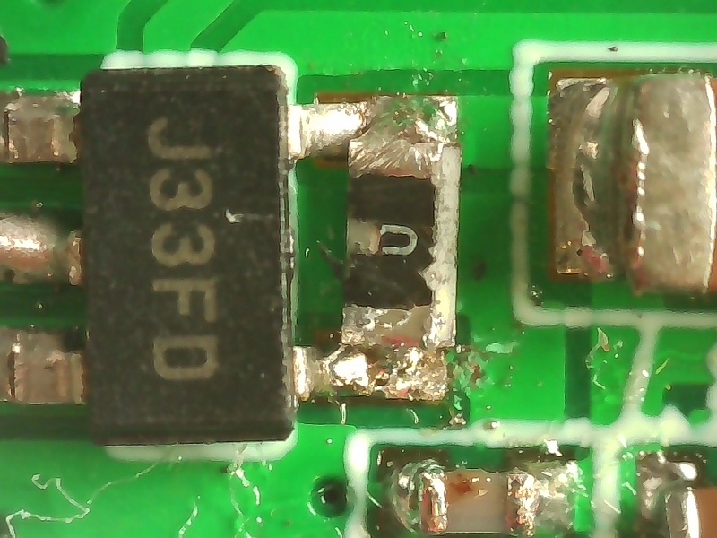
I also attached a zero ohm resistor to connect pin 4 and pin 5 of the LDO (low dropout, a component that creates a 3.3 volt power supply with a slight voltage drop from the 5 volt power supply) (reference: PocketSDR’s LDO Regulator, article by Professor Takuji Ebinuma of Chubu University).
In addition, a polyswitch is attached to the jumper terminal J2 that determines the power supply to the antenna terminal. For example, the satellite positioning module u-blox ZED-F9P can also control the antenna power on and off with commands, but I have not changed it from the initial state of on, and I think it is easier to use with it on (Reference: article Overcurrent protection for antenna feeding circuit (5V) by Professor Takasu).
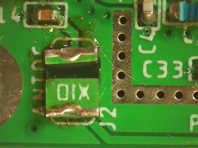
Finally, I attached the SMA connector to this board. I haven’t put the shield case on yet.
Powering and firmware writing
I powered the created Pocket SDR board, and confirmed that there was no short circuit in the power supply or antenna terminal with a tester, and connected the board USB terminal to the USB power supply. This is because I think that the USB power supply is safe because it can be expected that the power will be cut even in the unlikely event of a power short circuit. I made sure the green LED lighted up to indicate power and that there were 5 volts and 3.3 volts at the LDO terminals, then removed the board from the USB power supply.
After that, short the jumper terminal J2 (EEPROM) and reconnect the USB terminal of the board to the Windows PC. I have a lot of jumper pins, so I thought I wouldn’t have to buy them. However, the jumper pins needed here were not the 2.54 mm spacing often used in electronic work, but the 2 mm spacing. For the time being, I short-circuited this J2 with a test wire.
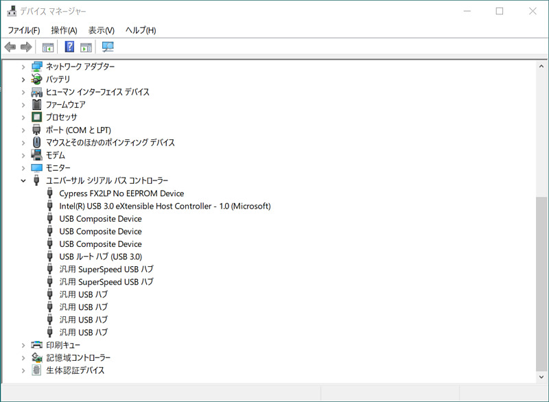
I connected the Pocket SDR board to the PC, ~~waited for 30 seconds, ~~ and started the device manager (I usually type devmgmt.msc from the keyboard to start it). Looking at this universal serial bus controller column, FX2LP of this USB controller IC was recognized as Cypress FX2LP No EEPROM Device. If it becomes an unknown device, right-click it, select Update Device Driver, and specify the directory of the previous USB driver CyUSB.
After that, I flush the Pocket SDR firmware (FW) to this FX2LP. I started CyControl.exe (USB Control Center) in the Pocket SDR directory FW/cypress/. At the USB Control Center, I selected Program, FX2, 64KB EEPROM in that order. Then, I specified the firmware binary pocket_fw.iic in the FW directory of Pocket SDR at the file selection dialog.
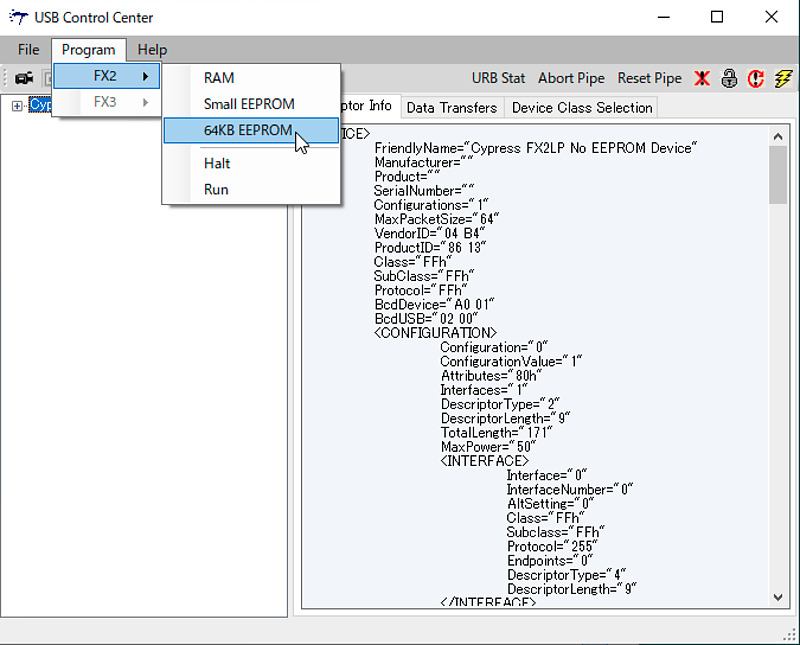
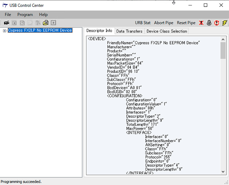
If you wait as it is, the letters “Programming succeeded” will be displayed at the bottom left of the USB Control Center screen. Actually, when I first tried to write the firmware with the J2 jumper left open, the result of Programming failed was displayed.
Here, once I removed the Pocket SDR board from the PC and connected it again, the two LEDs on the top glowed brightly.
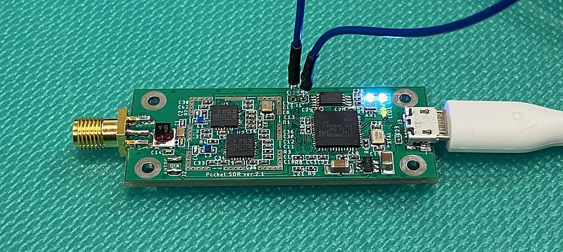
According to the Pocket SDR firmware code, LED1 indicates that USB bulk transfer mode is on, and LED2 indicates data transfer between the two MAX2771s. It seems that it always takes about 30 seconds to boot. (The reason why it took about 30 seconds to start was that some of the parts were not connected correctly, updated on 2022-09-14)
FW/pocket_fw.c
#define LED1         6          // EZ-USB FX2 PD6  -> LED1
#define LED2         7          // EZ-USB FX2 PD7  -> LED2
...
static void start_bulk(void) {
  ...
  digitalWrite(LED2, 1);
}
...
void setup(void) {
  ...
  start_bulk();
}
...
void loop(void) {
  // update LEDs
  digitalWrite(LED1, digitalRead(STAT1) && digitalRead(STAT2));
}
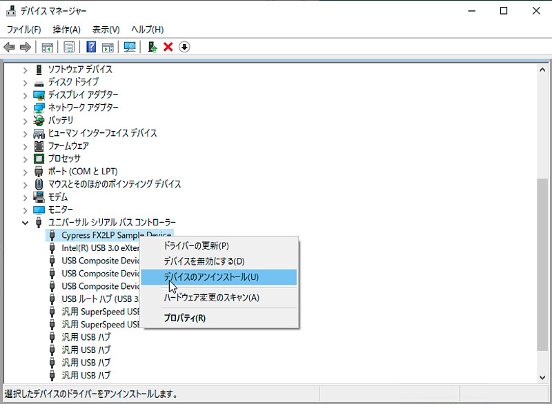
After successfully writing the firmware to FX2LP, the device name in the universal serial bus controller in the device manager will change from Cypress FX2LP No EEPROM Device to Cypress FX2LP Sample Device.
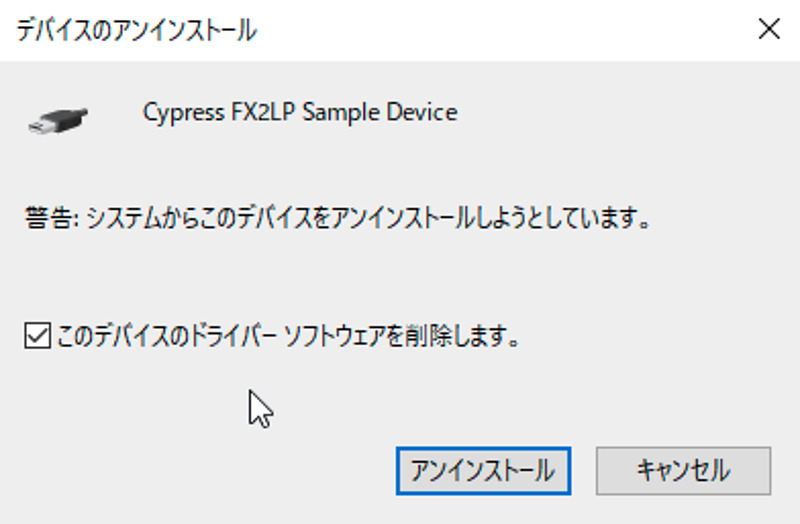
Next, uninstall this device driver and install the generic device driver zadig instead so that we can use this board from Pocket SDR applications (Reference: Prof. Takasu’s article, Host AP development environment for Pocket SDR production). Right-click and select Uninstall Device, then Delete Driver Software. Since Pocket SDR v.0.8 uses CyUSB as a driver for Windows, the following steps are unnecessary (updated on 2022-09-14).
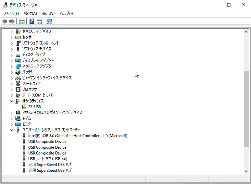
After uninstalling the Cypress USB device driver, the EZ-USB device appears with an error mark in “Other devices”.
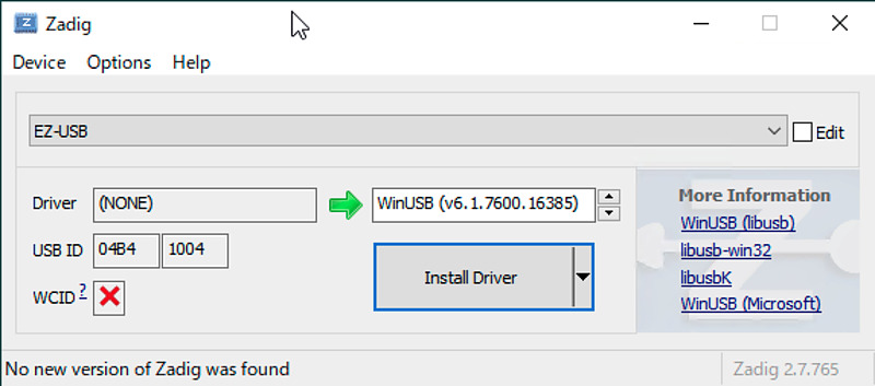
Then launch zadig downloaded earlier and install this USB driver on PC, and confirm the USB ID 04B4 1004 and press the Install Driver button.
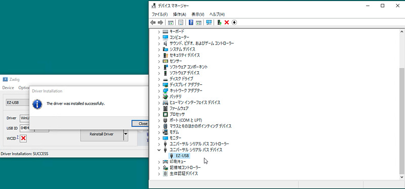
After successfully installing zadig’s device driver, the warning mark in Device Manager will disappear.
Hardware control from Pocket SDR application
Once we have done this, pass the path so that you can start the Pocket SDR application from such as the MSYS2 console and PowerShell.
My preference is to put shell scripts and Python code that work on all machines in bin in my home directory (synchronized with git), and put binaries that run on specific CPUs in exec in my home directory (copy with scp). Therefore, I copied the contents of Pokcet SDR’s bin directory to exec in my home directory, and I copied the contents of the python directory to bin directory in my home directory.
Then I run pocket_scan.exe to check the connection of the Pocket SDR board.
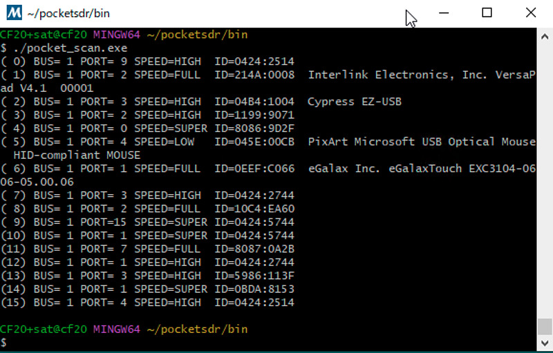
From this screen, Pocket SDR board (Cypress EZ-USB) is recognized in BUS=1, PORT=3.
Then I ran pocket_conf.exe, but it said No device found.. This code, without any options, looks for a device with USB ID 04B4 1004 and displays its settings. I specified the bus number and port number with the option -p 1,3 and ran pocket_conf.exe again, but the device was still not found.
I haven’t been able to confirm the operation of the MAX2771 yet, but I’m sure it’s one step closer. I hope to have it working soon. Please wait for the second report.
Pocket SDR is full of advanced know-how. You can acquire various knowledge just by chasing hardware and code.
Conclusion
Now that I have all the parts, I made the Pocket SDR hardware. I felt that preparation and preliminary investigation are very important for hardware production. Having good tools is also important. Acquire advanced knowledge at your own risk, and do not blame others for your failures. I am looking forward to the day when I can acquire navigation satellite signals with my Pocket SDR. Pocket SDR is awesome.
Related article(s):
- Awesome Pocket SDR (Effective use of configuration files) 30th April 2025
- Pocket SDR captured data 25th April 2025
- Awesome Pocket SDR (realtime positioning function) 13th October 2024
- Galileo E6B signal reception with Pocket SDR, a open source software-defined radio 27th January 2023
- Failure in reflow soldering 19th January 2023
- Pocket SDR hardware production (part 3) 30th September 2022
- Pocket SDR hardware production (part 2) 14th September 2022
- Awesome PocketSDR (order of hardware parts) 9th April 2022
- I want to use bladeRF with PocketSDR AP, part 2 16th March 2022
- I want to use bladeRF with PocketSDR AP 5th March 2022
- Awesome PocketSDR (snapshot positioning) 23rd February 2022
- Awesome PocketSDR (reducing processing time with FFTW) 19th February 2022
- Awesome PocketSDR (L6 band signal decode) 19th January 2022
- Awesome PocketSDR (pocket_trk) 28th December 2021
- Awesome PocketSDR(pocket_acq) 4th December 2021