Pocket SDR hardware production (part 3)
Completion of making Pocket SDR hardware
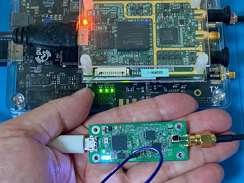
My Pocket SDR hardware worked. Pocket SDR is smaller than the board microcomputer Raspberry Pi Zero WH and much smaller than the software defined radios USRP B205mini-I and Nuand BladeRF, but it can receive GNSS signals very stably.
Malfunction reasons and how to fix them
My EEPROM malfunction was caused by incomplete connection of the pull-up resistor of the data line. Also, only one of the two white LEDs lit up was due to bad soldering on the power pin of the MAX2771 on one side. It seems that it worked correctly immediately after production, but that the soldering failure hidden in the dirt on the board caused a connection failure later.
I wiped off the flux stains with a Kimwipe, an industrial cotton swab, and a toothbrush soaked in absolute ethanol, and observed it under a microscope to find the defective soldering failure. I also used a flux remover.
To reattach a chip component that is suspected of having an incomplete connection,I warmed the entire component with a soldering iron while slowly sliding it off, wiped off the flux stains and reapplyed the new flux. On the other hand, I wiped off the parts with a Kimwipe dipped in absolute ethanol, picked them up with tweezers, and soldered them to the board with guts. Sometimes I was able to fix one point in about a minute, but sometimes it took more than 30 minutes to fix because the part stuck to the soldering iron and I needed to start over the flux-stain removal procedure.
When I picked up a chip component with tweezers, it flew out of the tweezers and I lost it. At that time, I removed the same parts from the failed printed circuit board and reused them. I made two sets of hardware at the same time and failed to make one of them, but in the end I’m glad I made two sets at the same time.
I almost gave up on Pocket SDR hardware production many times, but I accumulated know-how in the process of working on my own, and finally I was able to complete it. I’m happy.
Firmware for debugging
Professor Takuji Ebinuma of Chubu University taught me how to verify Pocket SDR operation without writing firmware to EEPROM (I am grateful the advice!). This is a method to transfer pocket_fw_debug.hex created in the PocketSDR Rebuild procedure to the FX2LP RAM area using the Cypress USB Control Center.
When this firmware is transferred to Pocket SDR’s FX2LP, this FX2LP disconnects itself from USB after the transfer, reconnects to USB, and works with the new firmware.
Thanks to this, I was able to use the USB functionality of my Pocket SDR hardware and found that the MAX2771 on one side was not working. From the Pocket SDR schematic, I can see that the data bus of the MAX2771 is shared. Nevertheless, since one MAX2771 works. According the face, I concentrated on checking the MAX2771 power supply connection and charge pump (voltage boost circuit) external component connection failure, and finally found a MAX2771’s power pin soldering failure.
Currently, this HEX file and pocket_fw_debug.iic, which was created together during the creation process, are written to EEPROM and used. I will replace this with Professor Takasu’s official firmware pocket_fw.iic.
Receiving QZSS MADOCA-PPP broadcast with Pocket SDR
Today, 2022-09-30, trial operation of QZSS (petnamed Michibiki) high-precision positioning augmentation service MADOCA-PPP (multi-GNSS advanced orbit and clock augmentation - precise point positioning) has started. MADOCA-PPP will be broadcast on QZSS’s L6E signal. I tried to receive this MADOCA-PPP on my Pocket SDR hardware.

The configuration file used this time is pocket_L1L6_12MHz.conf in the conf directory of Pocket SDR source tree. This L6 band signal is recorded by direct conversion (in-phase and quadrature signals) with a sampling frequency of 12 MHz. Using this setting, the L1 band signal and the L6 band signal are received simultaneously for 1 minute.
pocket_conf.exe ..\conf\pocket_L1L6_12MHz.conf
pocket_dump.exe -t 60
From the L6 band received signal file ch2_20220930_115617.bin (1.4 GB!) recorded in this way, Pocket SDR AP (application) extracts the message on the L6E signal and analyzes its contents with the QZS L6 Tool.
First, We check the Michibiki L6E signals that can be received with pocket_acq.py included in the Pocket SDR AP.
pocket_acq.py -sig L6E -prn 203-209 -f 12 ch2_20220930_115617.bin
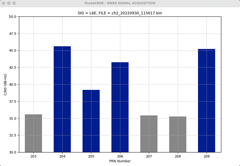
Based on this result, it seems that the L6E signal broadcast from all of QZSs (quasi-zenith satellites) of QZS-2 (PRN 204), QZS-4 (PRN 205), QZS-1R (QZS-1 replacement, PRN 206), and QZS-3 (geostationary satellite, PRN 209) can be received. Here, I adopt the L6E signal of PRN 204, which has the highest intensity, and observe the message while tracking the signal.
pocket_trk.py -sig L6E -prn 204 -f 12 -p ch2_20220930_115617.bin
The message decoded here will be displayed in the NAV DATA field. It seemed that many incoming messages contained many zeros. I saved this message in the file mdc.log with the -log option, convert it to L6 raw data with pksdr2l6.py of the QZS L6 Tool, and read the contents with qzsl62rtcm.py.
pocket_trk.py -sig L6E -prn 204 -f 12 ch2_20220930_115617.bin -log mdc.log
pksdr2l6.py < mdc.log | qzsl62rtcm.py

204 Hitachi-Ota:0  MADOCA-PPP
204 Hitachi-Ota:0  QZNMA
204 Hitachi-Ota:0  QZNMA
204 Hitachi-Ota:0  MADOCA-PPP
...snip...
204 Hitachi-Ota:0  MADOCA-PPP
204 Hitachi-Ota:0  MADOCA-PPP  SF1 DP1 (Clk/Eph LNAV) ST1 ST2...
204 Hitachi-Ota:0  MADOCA-PPP  SF1 DP2 (Clk/Eph LNAV) ST2...
204 Hitachi-Ota:0  MADOCA-PPP  SF1 DP3 (Clk/Eph LNAV) ST2 ST3
204 Hitachi-Ota:0  MADOCA-PPP  SF1 DP4 (Clk/Eph LNAV) (null)
204 Hitachi-Ota:0  MADOCA-PPP  SF1 DP5 (Clk/Eph LNAV) (null)
204 Hitachi-Ota:0  QZNMA
204 Hitachi-Ota:0  QZNMA
204 Hitachi-Ota:0  MADOCA-PPP  SF2 DP1 (Clk/Eph LNAV) ST7 ST3
qzsl62rtcm.py starts decoding CSSR (compact state space representation) information when it finds subtype 1 (ST1) data. I added the -t 1 option to display subtype data and the -s option to display statistical information to qzsl62rtcm.py and re-executed it.
pksdr2l6.py < mdc.log | qzsl62rtcm.py -t 1 -s

...snip...
ST1 G01 L1 C/A L1 Z-tracking L2 L2C(M+L) L2 Z-tracking L5 I+Q
ST1 G02 L1 C/A L1 Z-tracking L2 L2C(M+L) L2 Z-tracking
ST1 G03 L1 C/A L1 Z-tracking L2 L2C(M+L) L2 Z-tracking L5 I+Q
ST1 G04 L1 C/A L1 Z-tracking L1 L1C(D+P) L2 L2C(M+L) L2 Z-tracking L5 I+Q
ST1 G06 L1 C/A L1 Z-tracking L2 L2C(M+L) L2 Z-tracking L5 I+Q
ST1 G07 L1 C/A L1 Z-tracking L2 L2C(M+L) L2 Z-tracking
ST1 G08 L1 C/A L1 Z-tracking L2 L2C(M+L) L2 Z-tracking L5 I+Q
ST1 G09 L1 C/A L1 Z-tracking L2 L2C(M+L) L2 Z-tracking L5 I+Q
ST1 G10 L1 C/A L1 Z-tracking L2 L2C(M+L) L2 Z-tracking L5 I+Q
ST1 G11 L1 C/A L1 Z-tracking L2 L2C(M+L) L2 Z-tracking L5 I+Q
ST1 G12 L1 C/A L1 Z-tracking L2 L2C(M+L) L2 Z-tracking
ST1 G13 L1 C/A L1 Z-tracking L2 L2C(M+L) L2 Z-tracking
ST1 G14 L1 C/A L1 Z-tracking L1 L1C(D+P) L2 L2C(M+L) L2 Z-tracking L5 I+Q
ST1 G15 L1 C/A L1 Z-tracking L2 L2C(M+L) L2 Z-tracking
ST1 G16 L1 C/A L1 Z-tracking L2 L2C(M+L) L2 Z-tracking
ST1 G18 L1 C/A L1 Z-tracking L2 L2C(M+L) L2 Z-tracking L5 I+Q
ST1 G20 L1 C/A L1 Z-tracking L2 L2C(M+L) L2 Z-tracking
ST1 G21 L1 C/A L1 Z-tracking L2 L2C(M+L) L2 Z-tracking
ST1 G22 L1 C/A L1 Z-tracking L2 L2C(M+L) L2 Z-tracking
ST1 G23 L1 C/A L1 Z-tracking L1 L1C(D+P) L2 L2C(M+L) L2 Z-tracking L5 I+Q
ST1 G24 L1 C/A L1 Z-tracking L2 L2C(M+L) L2 Z-tracking L5 I+Q
ST1 G25 L1 C/A L1 Z-tracking L2 L2C(M+L) L2 Z-tracking L5 I+Q
ST1 G26 L1 C/A L1 Z-tracking L2 L2C(M+L) L2 Z-tracking L5 I+Q
ST1 G27 L1 C/A L1 Z-tracking L2 L2C(M+L) L2 Z-tracking L5 I+Q
ST1 G29 L1 C/A L1 Z-tracking L2 L2C(M+L) L2 Z-tracking
ST1 G30 L1 C/A L1 Z-tracking L2 L2C(M+L) L2 Z-tracking L5 I+Q
ST1 G31 L1 C/A L1 Z-tracking L2 L2C(M+L) L2 Z-tracking
ST1 G32 L1 C/A L1 Z-tracking L2 L2C(M+L) L2 Z-tracking L5 I+Q
ST1 R01 G1 C/A G1 P G2 C/A G2 P
ST1 R02 G1 C/A G1 P G2 C/A G2 P
ST1 R03 G1 C/A G1 P G2 C/A G2 P
ST1 R04 G1 C/A G1 P G2 C/A G2 P
ST1 R05 G1 C/A G1 P G2 C/A G2 P
ST1 R08 G1 C/A G1 P G2 C/A G2 P
ST1 R09 G1 C/A G1 P G2 C/A G2 P
ST1 R11 G1 C/A G1 P G2 C/A G2 P
ST1 R12 G1 C/A G1 P G2 C/A G2 P
ST1 R13 G1 C/A G1 P G2 C/A G2 P
ST1 R14 G1 C/A G1 P G2 C/A G2 P
ST1 R15 G1 C/A G1 P G2 C/A G2 P
ST1 R17 G1 C/A G1 P G2 C/A G2 P
ST1 R18 G1 C/A G1 P G2 C/A G2 P
ST1 R19 G1 C/A G1 P G2 C/A G2 P
ST1 R21 G1 C/A G1 P G2 C/A G2 P
ST1 R24 G1 C/A G1 P G2 C/A G2 P
ST1 E02 E1 B+C E5a I+Q
ST1 E03 E1 B+C E5a I+Q
ST1 E04 E1 B+C E5a I+Q
ST1 E07 E1 B+C E5a I+Q
ST1 E08 E1 B+C E5a I+Q
ST1 E11 E1 B+C E5a I+Q
ST1 E12 E1 B+C E5a I+Q
ST1 E13 E1 B+C E5a I+Q
ST1 E15 E1 B+C E5a I+Q
ST1 E19 E1 B+C E5a I+Q
ST1 E21 E1 B+C E5a I+Q
ST1 E24 E1 B+C E5a I+Q
ST1 E25 E1 B+C E5a I+Q
ST1 E26 E1 B+C E5a I+Q
ST1 E27 E1 B+C E5a I+Q
ST1 E30 E1 B+C E5a I+Q
ST1 E31 E1 B+C E5a I+Q
ST1 E33 E1 B+C E5a I+Q
ST1 E36 E1 B+C E5a I+Q
ST1 J02 L1 C/A L1 L1C(D+P) L2 L2C(M+L) L5 I+Q
ST1 J03 L1 C/A L1 L1C(D+P) L2 L2C(M+L) L5 I+Q
stat n_sat 66 n_sig 246 bit_sat 9608 bit_sig 6888 bit_other 831 bit_null 23353 bit_total 40680
...snip...
We could see that QZSS broadcast MADOCA-PPP augmentation information for 246 signals from 66 satellites then. Also, from the statistical information stat column, it broadcast 40,680 bits in 30 seconds of a frame. More than half of them, 23,353 bits, are currently null.
Conclusion
In order to determine the defective part, it is important to know how to modify the firmware and to imagine the defective part from the circuit diagram. With this completed Pocket SDR hardware, I was able to decode the message of the quasi-zenith satellite’s new augmentation information MADOCA-PPP, which was released today. I will attach a shield case to this hardware and enjoy receiving various GNSS signals.
Related article(s):
- Awesome Pocket SDR (Effective use of configuration files) 30th April 2025
- Pocket SDR captured data 25th April 2025
- Awesome Pocket SDR (realtime positioning function) 13th October 2024
- Galileo E6B signal reception with Pocket SDR, a open source software-defined radio 27th January 2023
- Failure in reflow soldering 19th January 2023
- Pocket SDR hardware production (part 2) 14th September 2022
- Pocket SDR hardware production (part 1) 4th September 2022
- Awesome PocketSDR (order of hardware parts) 9th April 2022
- I want to use bladeRF with PocketSDR AP, part 2 16th March 2022
- I want to use bladeRF with PocketSDR AP 5th March 2022
- Awesome PocketSDR (snapshot positioning) 23rd February 2022
- Awesome PocketSDR (reducing processing time with FFTW) 19th February 2022
- Awesome PocketSDR (L6 band signal decode) 19th January 2022
- Awesome PocketSDR (pocket_trk) 28th December 2021
- Awesome PocketSDR(pocket_acq) 4th December 2021