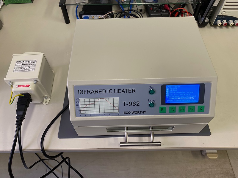
Small reflow oven T-962
Introduction
I am trying to create PocketSDR, a software defined radio for satellite positioning. Referring to Seeed Studio’s Fusion PCB blog (in Japanese) and Transistor Gijyutu, a Japanese maker magazine, I decided to purchase the reflow oven needed to solder small parts. I chose the T-962, which was small, inexpensive, and had many users.
Modification of T-962
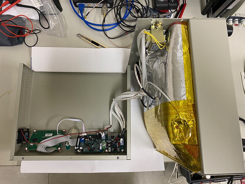
This T-962 is generally modified to use, and it seems that Unified Engineering’s T-962-improvements are widely used. I also tried to modify T-962 by referring to T-962 Reflow Oven Upgrades & Fixes on YouTube and web articles. The reasons for remodeling are as follows.
- Since paper tape is used inside and I am worried about heat resistance, I would like to replace it with Kapton tape.
- Since the ground terminal is not connected, I want to ground the housing.
- In order to improve the temperature setting accuracy, I want to use custom firmware, I want to introduce a chassis temperature (cold junction) sensor, and I want to change from analog reading to digital reading for the two existing temperature sensors.
- With a power supply of 100 volts in Japan, it takes time to raise the board temperature to 250 degrees Celsius, so I want to boost the power supply.
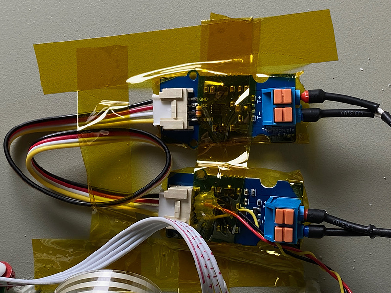
In addition, around 7 minutes 16 seconds of the previous YouTube article, there is a scene where the power supply and ground of the Maxim DS18B20 temperature sensor IC are combined into one and connected to the ground of the reflow furnace board. I was very surprised to drop the power supply terminal to the ground and wondered how this IC secures the power supply. It seems that this 1-wire has a mode that takes power from the signal line. In this mode, power is taken from the data line, stored in the capacitor of the sensor device, and used as power. It can be said that 1-wire applies the idea of bus connection, which shares the data line and ground line between multiple devices. When using this mode, the signal line must be pulled up to the power supply with a resistance of about 4.7 kiloohms. I attached this pull-up resistor to one of the two K-type thermocouple 1-wire interface Maxim MAX31850K breakdown boards and fixed these breakout boards to the T-962 body using Kapton tape.
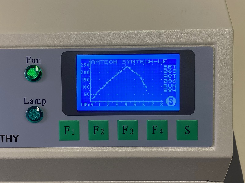
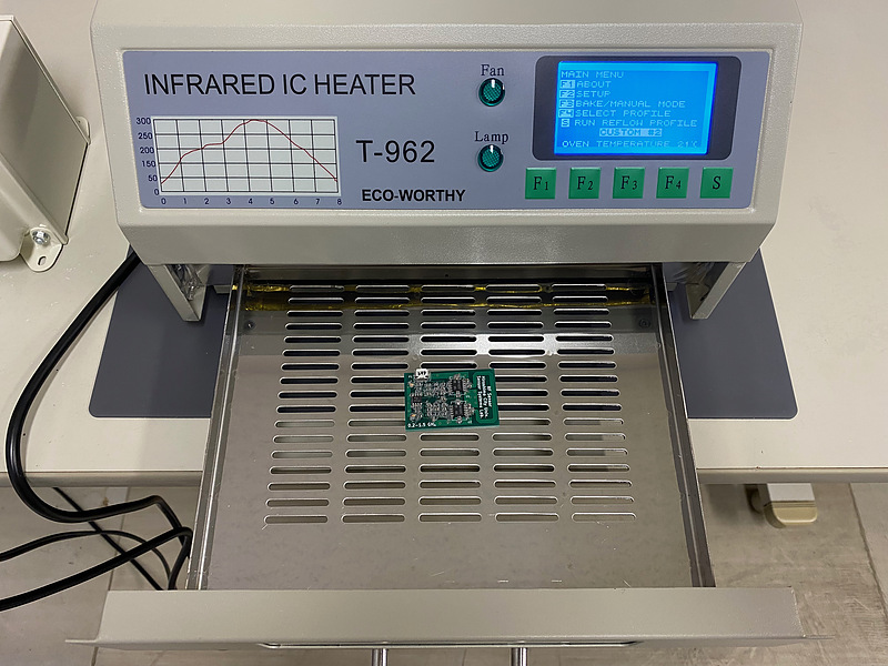
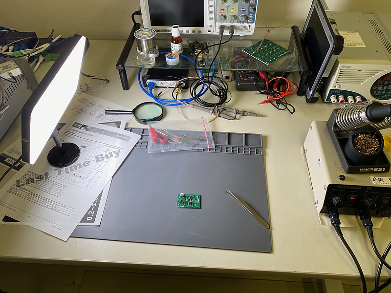
I did some test runs and confirmed that this T-962 is working well. The horizontal axis of the screen is the time in minutes, and the vertical axis is the set temperature in Celsius. The heater and fan follow the set temperature profile. It’s getting fun.
First reflow
Five years ago, while referring to the printed circuit board creation article of the Transistor Gijyutu, I used KiCAD, a board creation CAD (computer aided design) software. I remembered that I asked PCBWay, a Chinese company, to create a board with gerber data. I manually soldered two of the five boards I ordered at that time, but failed to make them and left them as they were. The board and parts at that time still remained, so I will use this to challenge the first reflow.
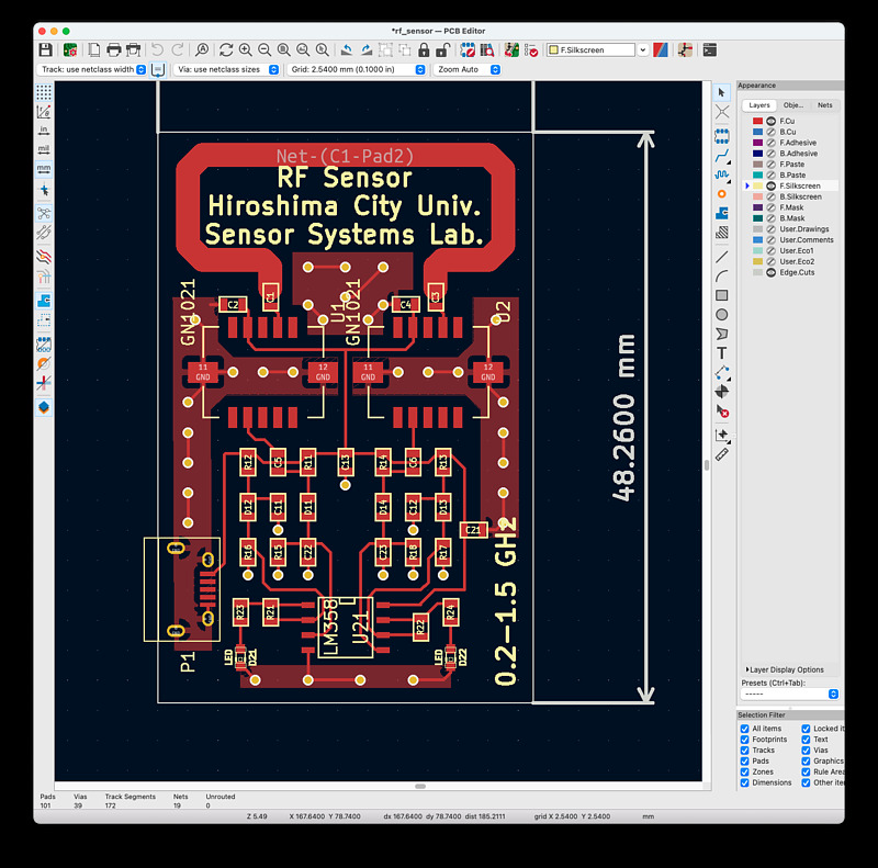
I changed the power pad on the board to a micro USB connector. I have the board at hand, but I don’t know the parts layout, so I started KiCAD for the first time in 5 years.
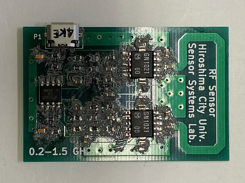
At that time, I wasn’t thinking about using a reflow oven at all, so I don’t have a metal mask (a mask with holes for putting cream solder on the copper foil surface, which is also called a stencil). So, I used a cotton swab and a drill to apply cream solder to the copper foil surface of the printed circuit board. Of course, there are places where the solder squeezes out or is not painted. During the reflow process, I thought that the cream solder would collect only on the copper foil surface, so I proceeded with the work.
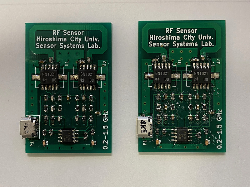
The board on the left side of the photo is the one created by manual soldering, and the board on the right side is the one created this time. Regarding the USB micro connector on the lower left of the board and the amplifier IC on the top of the board. In particular, I remembered that this USB micro connector had terminals inside the housing and it was very difficult to solder.
There are 3 places failed to solder through this reflow process, so I will fix it using a soldering iron.
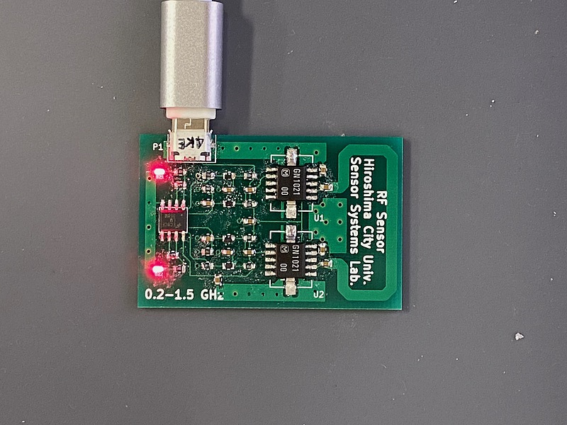
After conducting the same test with a tester, power was supplied to this radio wave sensor from the micro USB terminal. If there is a radio wave in the sensor part, the LED in the direction of the flow should be lit, but both LEDs are still lit. Why?
When I saw the display of the power supply line voltage “minus 5 volts” measured with a tester, tears came out. Even so, the LED turned on because I forgot to print the LED polarity when I made the board, so I placed the parts while checking the polarity.
Get more experience
It seems that the reflow was successful, but the work failed. It was a little fun.
Someday, I want to be able to make PocketSDR and the snapshot receiver of Prof. Takasu.