Failure in reflow soldering
I want to make additional Pocket SDR hardware
I’m happy to be able to produce, a super special ultra-high-performance GPS receiver “Pocket SDR Hardware”, and I thought I’d make three more. Hope comes to me.
I was able to freely remove parts such as ICs from boards that I failed to make, and attach them to other boards, and gained confidence in detailed work.
Use of lead-free solder
In the midst of this shortage of semiconductors, I managed to obtain a PC communication IC (Infineon CY7C68013A) and a satellite signal reception IC (Analog Devices MAX2771ETI), and also ordered additional parts such as resistors and capacitors. Since there are many small parts, it took about 5 hours to put the parts on the 3 boards.
It is said that even if the position where the component is placed is slightly misaligned, it is automatically corrected to the correct position when soldering (reflow) by applying high temperature to the board (it also referred to as auto alignment). However, I aimed for a one-shot operation without correction, I made corrections in 0.1 mm increments with tweezers.
This time, I used eco-friendly lead-free cream solder. I should have done it, but I did something out of the ordinary. Since it was getting fun, I suddenly reflowed all three printed circuit boards without doing any trial work.
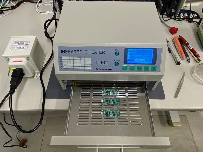
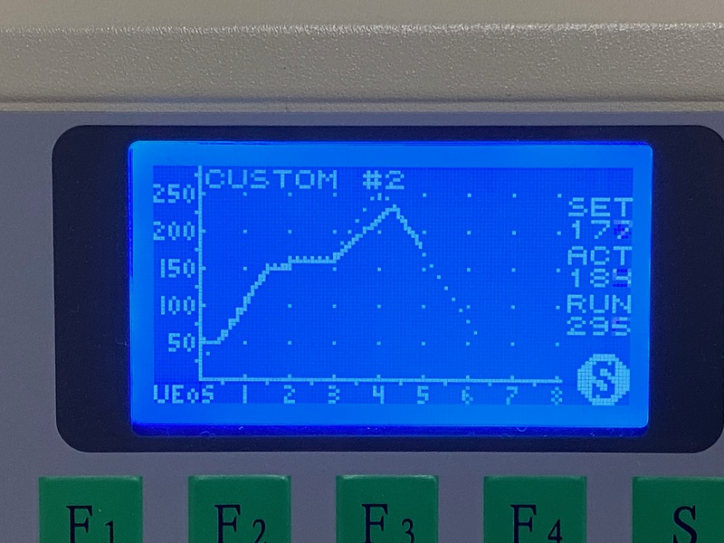
Oh, I forgot to review the temperature profile (the temperature setting that changes sequentially over time) even though I changed the solder paste used. Well, maybe because of the low ambient temperature, it doesn’t reach the standard maximum temperature of 250 degrees Celsius. In general, lead-free solder has a low melting point, so I had a premonition of failure.
Failure in reflow
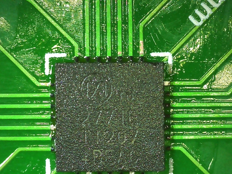
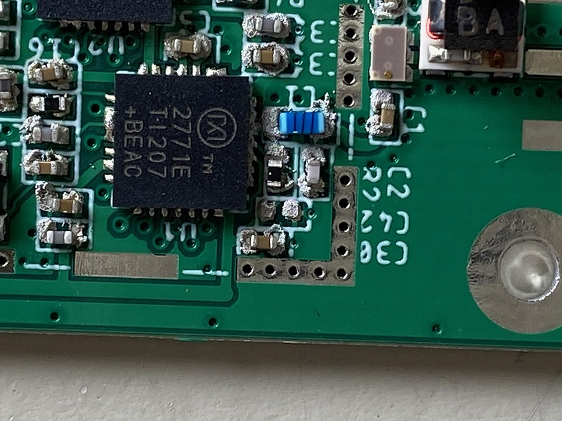
I had a bad feeling, and as we can see in this photo, the solder is not melted and does not shine. This is a failure. It’s getting interesting. This is the lecture that God gave me.
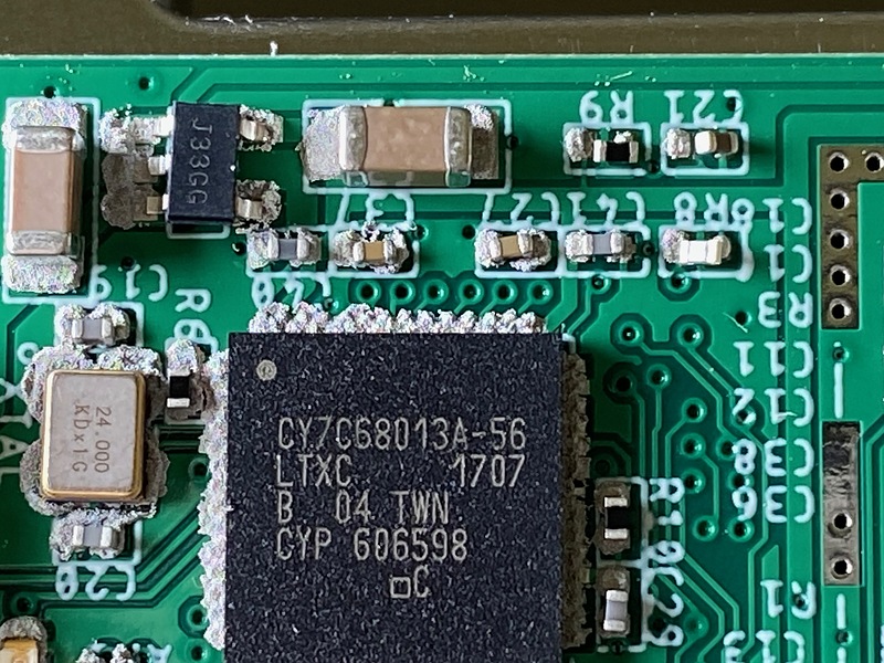
The capacitor C42 that should be on the bottom right of this MAX2771ETI disappeared somewhere.
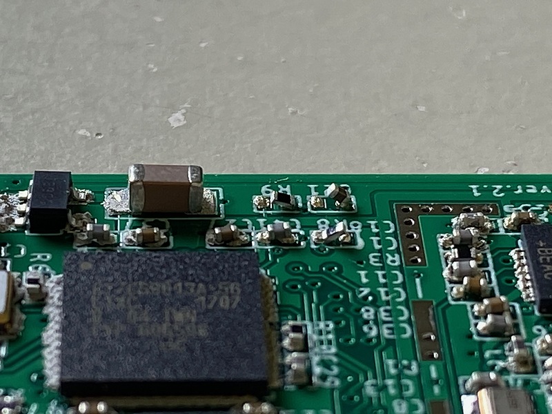
The resistor R9 and the capacitor C21 at the top of this photo are bowed (but I can fix them easily :-).
I’m full of sad feelings, but I’ll do my best to fix it from now on. I’m going to apply flux (a soldering accelerator) to the solder and try reflowing again. Of course, this time I will work one by one.
Using Pocket SDR hardware on Linux
Normally I have my Pocket SDR hardware connected to my Linux PC. If you save the following content in /etc/udev/rules.d/ with a file name such as 00-pocketsdr.rules, you can access the hardware even if you are not root. convenient.
# FX2
SUBSYSTEM=="usb",\
    ATTR{idVendor}=="04b4", ATTR{idProduct}=="1004",\
    GROUP="plugdev", MODE="0660"
From Pocket SDR v.0.8, CyUSB is used as the hardware driver. Currently, I’m trying to make the Linux driver compatible with CyUSB.
Related article(s):
- Awesome Pocket SDR (Effective use of configuration files) 30th April 2025
- Pocket SDR captured data 25th April 2025
- Awesome Pocket SDR (realtime positioning function) 13th October 2024
- Galileo E6B signal reception with Pocket SDR, a open source software-defined radio 27th January 2023
- Pocket SDR hardware production (part 3) 30th September 2022
- Pocket SDR hardware production (part 2) 14th September 2022
- Pocket SDR hardware production (part 1) 4th September 2022
- Awesome PocketSDR (order of hardware parts) 9th April 2022
- I want to use bladeRF with PocketSDR AP, part 2 16th March 2022
- I want to use bladeRF with PocketSDR AP 5th March 2022
- Awesome PocketSDR (snapshot positioning) 23rd February 2022
- Awesome PocketSDR (reducing processing time with FFTW) 19th February 2022
- Awesome PocketSDR (L6 band signal decode) 19th January 2022
- Awesome PocketSDR (pocket_trk) 28th December 2021
- Awesome PocketSDR(pocket_acq) 4th December 2021