MA-10P and DGM10-PPP GNSS receivers
Introduction
I bought some new GNSS receivers: the MA-10P and DGM10-PPP sold by DATAGNSS. Both models I purchased support CLAS, the high-precision positioning service provided by the Quasi-Zenith Satellite System (QZSS), Michibiki. They can perform high-precision positioning on their own and output the results in the standard NMEA 0183 format.
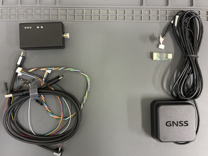
I still use a receiver with an HD9310 Option C module that the company used to sell. I have high hopes for these two new receivers as well.
MA-10P and DGM10-PPP
The main difference between the MA-10P and DGM10-PPP is whether the antenna is built in. The MA-10P uses an external antenna, while the DGM10-PPP combines the antenna and receiver in a single unit.
Combining GNSS positioning signals with external information to improve positioning accuracy and other aspects of performance is called augmentation. Some designs receive positioning and augmentation signals within a single module, while others use separate modules for each. Both receivers reviewed here contain a D10P GNSS receiver module and a QZS-6C module for receiving Michibiki augmentation information. An internal splitter divides the signal from the antenna and feeds it to the two modules.
Michibiki’s augmentation services for high-precision positioning include CLAS and MADOCA-PPP. CLAS is specifically designed for use in Japan. Each receiver is available in CLAS and MADOCA-PPP versions, giving the following four options. I purchased the CLAS version of both receivers.
| Supported service | External antenna | Integrated antenna |
|---|---|---|
| CLAS | MA-10P CLAS | DGM10-PPP CLAS |
| MADOCA-PPP | MA-10P MADOCA/PPP | DGM10-PPP MADOCA/PPP |
The MA-10P I received was the MA-10P V2 (MA10P-V2-CLAS), which supports Michibiki No. 6, and it came in an enclosure.
DGM10-PPP CLAS
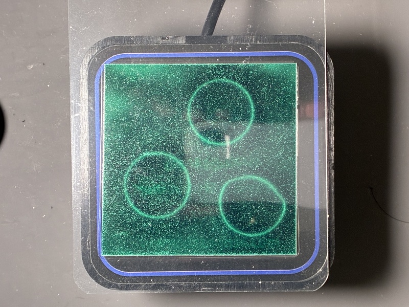
The DGM10-PPP CLAS unit measures 65 mm wide, 65 mm deep, and 25 mm high. Since the CLAS and MADOCA-PPP versions look the same, I attached a label to identify mine.
The unit I received has an approximately 3 m cable ending in a six-pin JST connector. It also comes with a USB-to-serial adapter board for connection to a PC’s USB-C port.
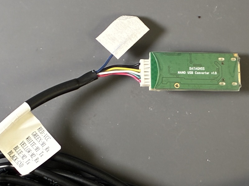
The six wires from the unit were labeled to identify the power connections and the transmit and receive lines for two serial interfaces, M1 and M2. Since the M2 transmit line is unconnected, I suspect that M1 connects to the D10P and M2 to the QZS-6C. However, when I connected the supplied USB-to-serial adapter board to a PC, only one serial port was detected. This was a little disappointing, as I had hoped to inspect the augmentation information from the QZS-6C as well. The supply voltage was 5 V.
There are three magnets on the underside of the unit. To improve reception, the product documentation linked above recommends placing the unit on a metal surface with a diameter of at least 100 mm as a general guideline.
After placing the unit near a window and setting the serial port to 230400 baud, I could see NMEA 0183 messages. I installed the official Satrack software on a Windows PC to check reception, and it displayed an L6D signal for satellite number “2.” I have not yet confirmed whether this number refers to QZS-2.

I hope that this receiver, which uses an Allystar chip, can also demodulate multiple L6 signals simultaneously. I plan to place the antenna where it has a clear view of the sky and check whether it can receive multiple L6 signals at once. I would also like to investigate whether L6 data can be extracted as it can with the HD9310 Option C, and what data passes through the two serial interfaces on the JST connector.
MA-10P
The MA-10P V2 uses an external antenna and provides Wi-Fi and BLE (Bluetooth Low Energy) interfaces. It also has a web interface accessible over Wi-Fi. The circuit board appears to have changed from version 1 to version 2. Like the DGM10-PPP, it also has a six-pin JST connector.
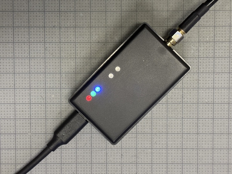
The MA-10P has two buttons and three LEDs. The buttons currently have no functions assigned to them. After connecting an antenna to the unit and connecting its USB-C port to a PC, the PC detected two serial ports. The main port runs at 230400 baud and the auxiliary port at 115200 baud. I could see NMEA 0183 messages on the main port.
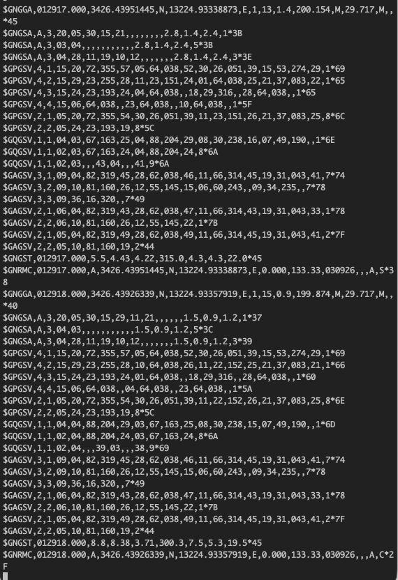
Connecting the PC to the NANO_RTK Wi-Fi access point and opening http://192.168.4.1/ in a browser displayed the web interface. It appears to share an interface with DATAGNSS’s NANO RTK Receiver.
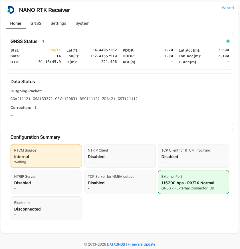
The GNSS tab is shown below. As far as I could tell, settings could not be changed from this tab.
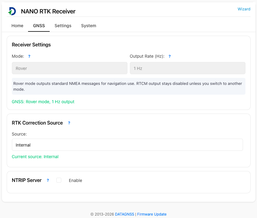
The Settings tab appears to allow configuration of the Wi-Fi access point. After clicking the TCP server option, I connected from the PC by running nc 192.168.4.1 9009 and could see NMEA 0183 messages.
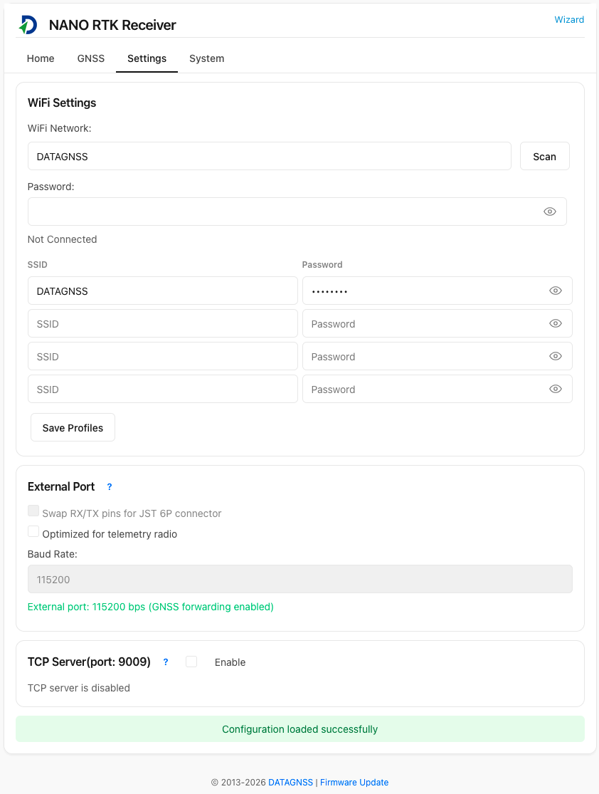
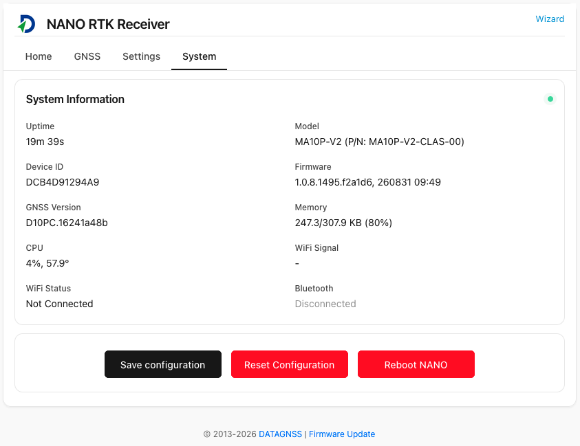
The System tab displayed the uptime, model name, CPU usage, temperature, and other information.
Clicking Wizard at the top of the page opened the Advanced Settings menu.
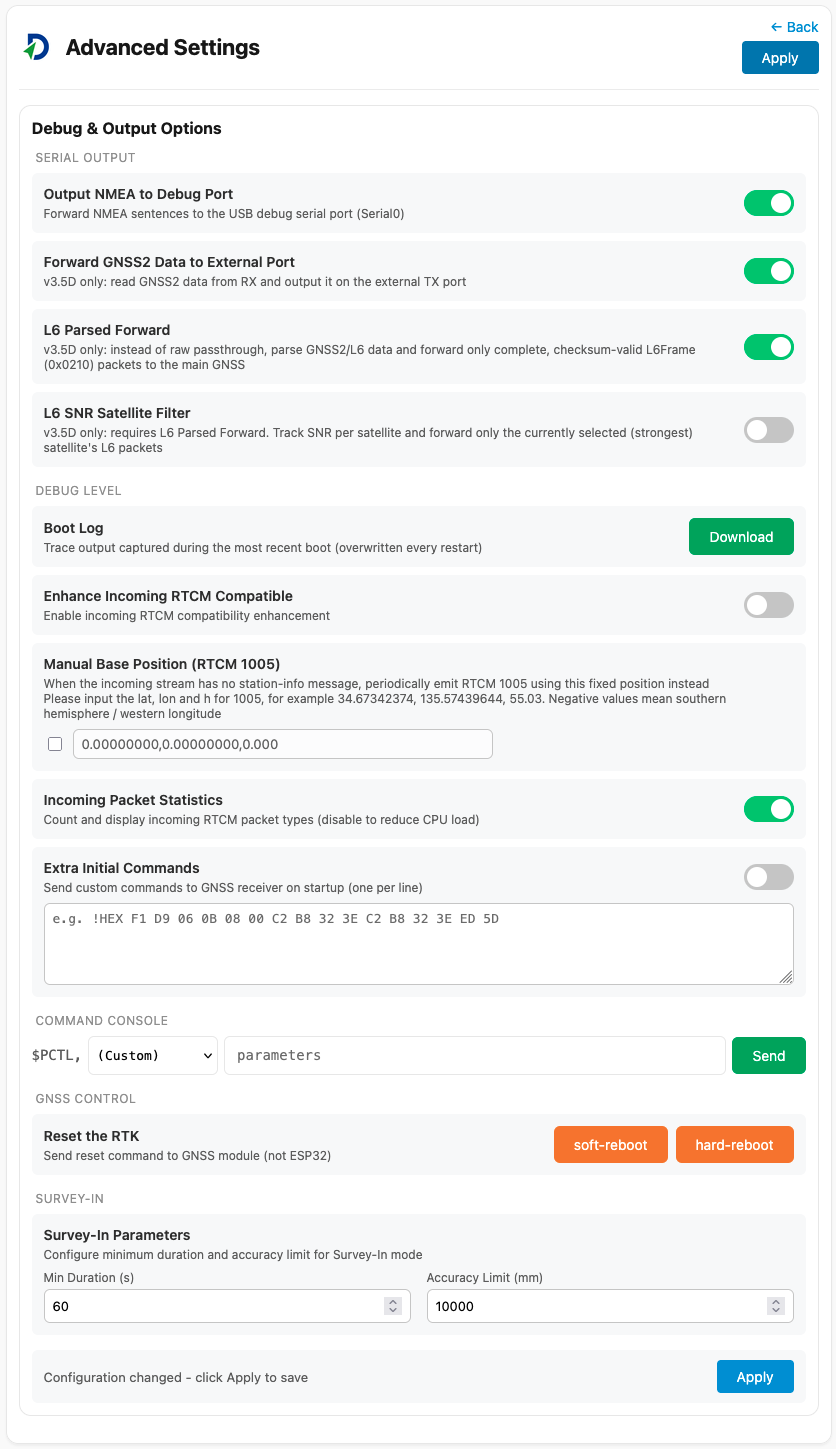
Using this menu, I was able to configure the unit to output NMEA 0183 messages on the auxiliary port as well. However, with the settings I tried, I could not confirm any output of QZS-6C augmentation information from that port either.
After a while, the LED indicated a fixed solution. I also plan to investigate the serial data on the MA-10P’s JST connector.
Conclusion
I tried the CLAS versions of the DGM10-PPP and MA-10P. Both are appealing because they can perform high-precision positioning using CLAS on their own. This initial check focused mainly on connection methods and data output. I have not yet evaluated positioning accuracy, so I plan to use both receivers under various conditions to investigate their positioning performance and the serial data on their JST connectors.
Related article(s):
- New evaluation board for Allystar HD9310 14th October 2020
- Quasi-zenith satellite CLAS augmentation information extraction using Allystar HD9310 Option C 28th September 2020
- Allystar HD9310 Firmware Update 22nd June 2020
- Experiment of Allystar HD9310 22nd November 2019