New evaluation board for Allystar HD9310
HD9310 new evaluation board with changed design
The quasi-zenith satellite (QZS), or Michibiki, broadcasts not only positioning signals but also its highly accurate augmentation signals. In order to receive this CLAS (centimeter level augmentation system, it pronounces as Cirrus) signal and MADOCA (multi-GNSS advanced demonstration tool for orbit and clock analysis) signals, we need receiving the frequency at 1278.75 MHz, called L6-band.
The Allystar HD9310 is currently the cheapest chip to receive this L6 band signal. So far, I have tried the HD9310 evaluation board (Experiment of Allystar HD9310, Allystar HD9310 Firmware Update, and Quasi-zenith satellite CLAS augmentation information extraction using Allystar HD9310 Option C). What I actually used was the DATAGNSS receiver module TAU1302 equipped with HD9310. When I purchased this evaluation board additionally, the layout of the board was updated.
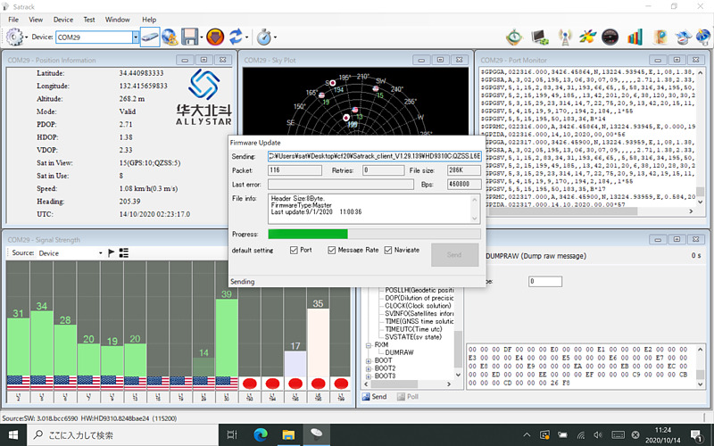
The HD9310 has two types of firmware, one is for receiving CLAS signal and another is for receiving MADOCA signal. This evaluation board was applied the latest firmware 3.018.bcc6590 for CLAS signal reception available on the DATAGNSS Home Page.
1-PPS display LED disappeared and lithium battery charging function was installed
On the old Board, there were four LEDs: 1-PPS (pulse-per-second), power supply, USB port TXD (transmission data), and RXD (reception data). However, the 1-PPS LED on the old board remained off. In addition, there was a switch to set whether to supply power to the antenna on old board.
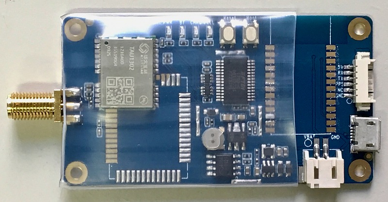
This is the new board. It is now covered with heat shrink tubing for insulation. In addition, the connector on the upper right had the following markings.
| pin number (left to right) | marking |
|---|---|
| 1 | GND |
| 2 | NC |
| 3 | PPS |
| 4 | TX |
| 5 | RX |
| 6 | 5V |
I’m glad that the signal can be taken out. In addition, a JST PH 2-pin connector, which seems to be used for connecting lithium-ion batteries, has been added to the lower right of the new board. We can see the marks VBAT and GND near the connector. The open circuit voltage of this connector terminal was measured and found to be 1.8 V, and it seems that the voltage is low to charge the lithium-ion battery. The model number of the battery management IC could not be read.
In addition, this new board is equipped with a capacitor for storing ephemeris, which was not found on the old board. With the new board, we can reduce the time from turning on the power again to starting positioning.
On the other hand, the LEDs have been consolidated in the upper center of the board and changed to power supply (PWR), Bluetooth (BT), charging (CHRG), and charging complete (FULL). In addition, the power supply switch to the antenna has been abolished. This evaluation board does not have a Bluetooth communication function, and it is unknown how to use this battery charging function, so the previous one was better for LEDs.
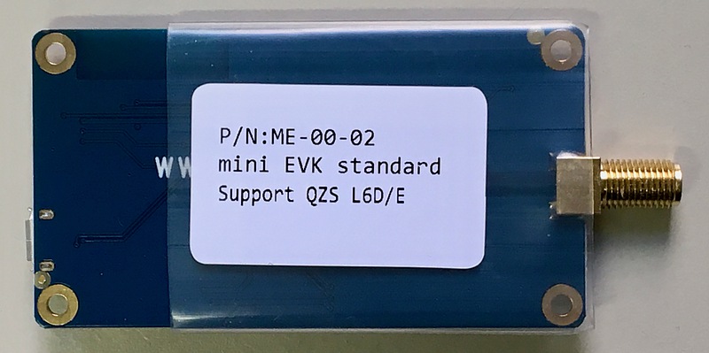
This is the back of the new board. There are letters L6D for the CLAS signal reception function and L6E for the MADOCA signal reception function.
Also, the USB serial port device has changed between the old board and the new board. The old board used Silicon Labs. CP210x, while the new board uses FTDI.
Satellite signal reception with a antenna close vicinity to window
At the bottom of my laboratory window, I placed an antenna capable of receiving both the L1 frequency band (1575.42 MHz) and the L2 frequency band (1227.6 MHz), and received this L6 band (1278.75 MHz) satellite signal. The L2 band lies between the L6 band and the L5 band (1176.45 MHz). Therefore, I expected that the L6 band signal could be received using the popular L2 band antenna. There is an antenna on the roof of the university that can receive the L6 band, but here I tried L6 band reception with an antenna that can receive both the L1 band and the L2 band. The first is an unidentified quadruple helix antenna.
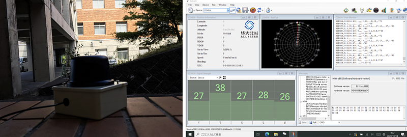
The result was that only some of the GPS signals could be received. Next, I connected TOPGNSS’s GN-GGB0710 to the receiver.
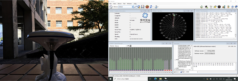
Many GPS and Michibiki L1 band signals can now be received, but Michibiki L6 band signals could not be received. The next antenna is u-blox ANN-MB-00.
Compared to the previous antenna, this antenna can receive fewer satellites. In general, larger antennas seem to be able to receive more satellite signals. After all, the L6 band signal could not be received this time.
Firmware update for receiving MADOCA augmentation signal
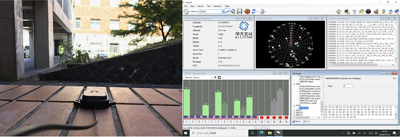
I am continuously observing CLAS signals on the old board. Therefore, I decided to receive the MADOCA signal on this new board, so I updated the firmware to that of MADOCA. The software version after the firmware update was 3.018bcc6590, which was the same as that of the previous CLAS.
This new board was also installed on the roof of the university. This is a picture of the old and new HD9310 evaluation boards.
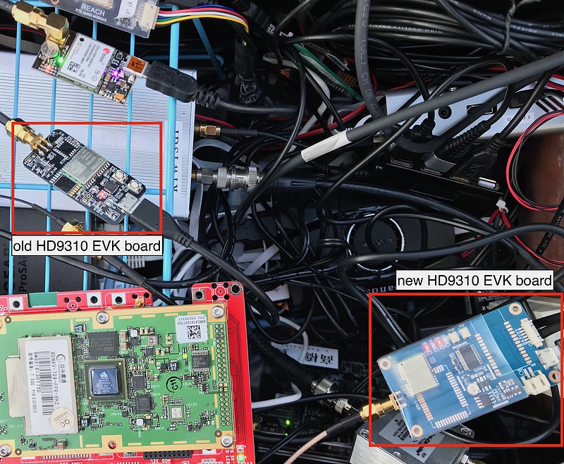
The new board is about twice as large as the old board. The old board was about the same size as the Emlid REACH RTK, so the new board was disappointing in terms of size.
The termination of providing MADOCA augmentation information service via the Internet of JAXA (Japan Aerospace Exploration Agency) was announced in January 2020. However, it is still being delivered at this time. In addition, the Global Positioning Service (GPAS) launched the MADOCA distribution service on the Internet in January 2020. I also applied for the MADOCA distribution service by GPAS. When the MADOCA augmentation information of JAXA and GPAS is applied to the RTK reference station data, the coordinate values are slightly different. I would like to compare these three MADOCA augmentation information including those broadcast from Michibiki before the end of MADOCA distribution from JAXA.
According to page 16 of slide at CGSIC in September 2020 by Dr. Kogure of the Cabinet Office of Japan, it seems that Michibiki Unit 6 will be placed over the Indian Ocean (S. Kogure, QZSS Update, CGSIC International Session, September 21, 2020). There was a link in the article by Professor Takasu of Tokyo University of Marine Science and Technology on September 23, 2020. Just as the tripod is more stable with its legs open, it is possible to secure this geosynchronous orbit because the positioning satellites at geographically separated locations can improve the position observation accuracy. I think Michibiki is moving in a technically interesting direction.
Related article(s):
- Quasi-zenith satellite CLAS augmentation information extraction using Allystar HD9310 Option C 28th September 2020
- Allystar HD9310 Firmware Update 22nd June 2020
- Experiment of Allystar HD9310 22nd November 2019