Circularly polarized antenna experiment (failed)
Introuction
Radiowaves are transverse waves. The electric field is generated perpendicular to the direction of travel. In the past, analog TV receiving antennas in Japan were installed horizontally to the ground and captured horizontally polarized radiowaves. Current Japanese terrestrial digital broadcasting uses a mixture of vertical and horizontal polarization. Vertical polarization is primarily used in mobile radio communications.
Circularly polarized waves, whose plane of polarization rotates over time, are used when transmitting signals using radiowaves between space and the earth, such as in GPS positioning. This is because horizontal and vertical cannot be defined here with respect to the earth’s ground.
This time, I conducted an experiment to transmit and receive circularly polarized radiowaves, taking care not to leak radiowaves to the outside.
Right-handed and left-handed circularly polarized radiowaves
Radiowaves with different polarization cannot be received. However, for example in land mobile radio communications, the plane of polarization rotates during radiowave propagation processes such as reflection and scattering, so it may be possible to receive radiowaves even if they have different polarizations. Still, mismatched polarization between transmitter and receiver weakens the signal strength.
Just as linear polarization has vertical polarization and horizontal polarization, circular polarization also has right-hand circular polarization (RHCP) and left-hand circular polarization (LHCP). Similar to linearly polarized waves, polarization mismatch in circularly polarized waves results in a reduction in received signal strength. For example, GPS satellites are supposed to broadcast RHCP radio waves.
Radiation of circularly polarized radio waves can be achieved using helical antenna, wavelength plate tilted at 45 degrees, turnstile antenna with 90 degree phase shift and two-point feeding, microstrip antenna using degenerate separation element.
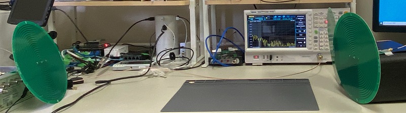
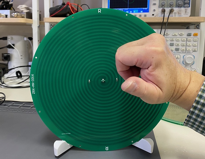
The equipment used here was two RHCP antennas, one LHCP antenna, one coaxial cable switch, and a network analyzer. A network analyzer is a device that transmits and receives high-frequency waves while sweeping the frequency, and measures amplitude and phase. As a circularly polarized antenna, I used an Archimedean (spiral) antenna that can be used in a wide band. I bought an Archimedes antenna available from 400 MHz to 10 GHz, but later I bought a smaller and cheaper one is on sale. Because I want to observe a variety of radiowaves, I’m satisfied with this antenna.
The polarization of the Archimedes antenna in the photo below is RHCP. When the thumb of the right hand is pointed in the direction of radiowave emission, the other fingers emit radiowaves while rotating the polarization in the direction in which they bend.
In order to receive this RHCP radiowave, an antenna with LHCP configuration is used. The hands of a clock rotate clockwise, but on the back of the clock they appear to rotate counterclockwise. Similarly, when the receiving antenna is directly facing the transmitting antenna, the receiving antenna faces in the opposite direction to the direction of radiowaves, so the received polarization is observed to be reversed relative to the transmitting polarization.
When a radiowave is reflected vertically from such as a wall, the direction of propagation of the radiowave is reversed, but the polarization rotation itself is preserved, so an inverted polarization is observed. However, circularly polarized radiowaves become elliptically polarized radiowaves due to oblique reflection, and have both RHCP and LHCP components. In particular, when the RHCP level and LHCP level match, the signal becomes linearly polarized, and when received with a circularly polarized antenna, the radio field strength is 3 decibels weaker than when received with the same polarized antenna.
The trouble is that in the world of radiowaves, the receiving antenna is supposed to display the sender’s polarization. For example, an antenna that receives GPS RHCP radiowaves is written as RHCP. Furthermore, in the optical world, it is supposed to display the polarization of the receiver side, which is confusing.
The impedance of a printed circuit board line (microstrip line) increases as the line width becomes narrower. Observing this antenna, we can see that the junction between the matching circuit and the spiral antenna section is very thin, so the impedance of this antenna section at resonance is very high. The Archimedes antenna has a large impedance match circuit, making it inconvenient to carry and store.
Antenna measurements
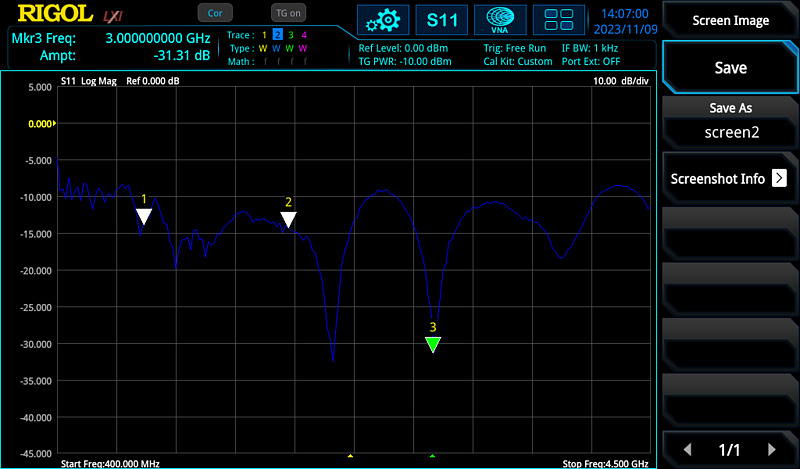
Now set the network analyzer to S11 scattering parameter measurement mode. This is a mode in which radiowaves are emitted from port 1 of a network analyzer, the radiowaves are received at the same port 1, and the amplitude and phase are measured. If this relative amplitude is small, either the radiowaves are being radiated into space well, or the antenna’s internal resistor is consuming power.
This antenna is supposed to be available up to 10 GHz, but due to limitations of this network analyzer, I have set the upper frequency limit to 4.5 GHz. This display is called a LogMag (logarithmic magnitude) display, and the horizontal axis represents the frequency, and the vertical axis represents the power absorbed and emitted by the antenna in decibels. The smaller the value on the vertical axis, the better the radiowaves are radiated, which makes me happy. As reference, marker 1 is set to 1 GHz, marker 2 to 2 GHz, and marker 3 to 3 GHz. The LogMag value was approximately -10 dB or less over the frequency range from 400 MHz to 4.5 GHz. This is considered to be a good characteristic as more than 90% of the total power is radiated as radiowaves.
Next, change the settings to Smith chart display. This shows the impedance locus with respect to frequency changes, with the resistance component to the left of the horizontal axis and the positive reactance component to the clockwise direction. Since the impedance standard is set to 50 ohms, the impedance matching is such that this locus converges at the impedance 50+j 0 ohm point in the center, and this antenna can be used in a wide band. On the other hand, when port 1 is open or shorted, the resistance or reactance component increases, so this trajectory sticks to the outer periphery.
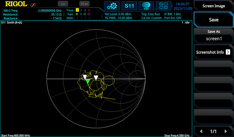
Actually, out of the three antennas I purchased, one had a broken connection between the matching circuit and the spiral antenna part. I noticed this break when I looked at the Smith chart. Therefore, I used a drill tip to drill a 0.8mm hole near this connection, connected it with a lead wire, and repaired it. A network analyzer is a very expensive measuring instrument, but it’s definitely something you’ll want to own for troubleshooting purposes. I also have a cheaper network analyzer SV6301 (1 MHz-6.3 GHz). It’s small, lightweight, has a built-in rechargeable battery, and comes with the necessary calibration kit, which I use for outdoor measurements. I also have a small network analyzer SARK-110 (100 kHz-230 MHz).
Circularly polarized antenna transmission experiment
Now put the network analyzer in S21 mode. This is a mode in which radiowaves are emitted from port 1 and received at port 2, and the attenuation and phase rotation between these ports are measured. Here, I connected the RHCP antenna to port 1. On the other hand, I connected a coaxial cable switch to port 2 to be able to switch between the LHCP antenna and the RHCP antenna, making it easier to compare the characteristics. The distance between the transmitting and receiving antennas is approximately 80 cm.
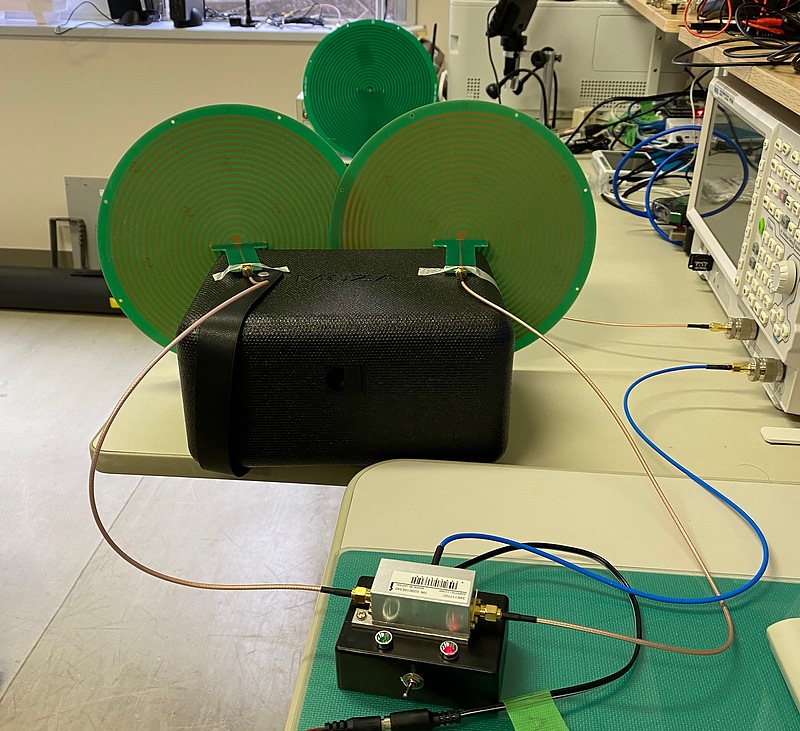
Here the two receiving antennas are touching. When measuring the S11 scattering parameters, the characteristics did not significantly change much even when the antenna element was touched, so I believe that the effect of contact is minor.
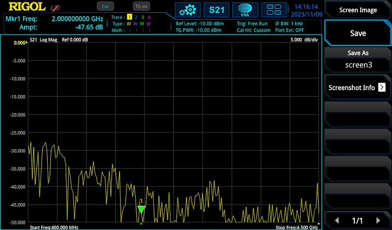
First, the radiowaves from this RHCP antenna are received by the LHCP antenna. I set the display to LogMag and set the marker to 2 GHz as an example. The horizontal axis represents frequency, and the vertical axis represents propagation loss between transmitter and receiver. The propagation loss at the marker frequency is 47.7 dB, which is very large.
Then I switched to RHCP antenna reception. The propagation loss was 31.5 dB.
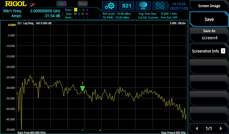
Radiowaves emitted by RHCP are received by LHCP, and should be difficult to receive by RHCP. Here, the result was the opposite.
If we place the transmitting RHCP antenna behind the receiving antenna, the reception level of the RHCP antenna should exceed the reception level of the LHCP antenna. But it didn’t turn out that way.
I do not know why. I may be misunderstanding something.
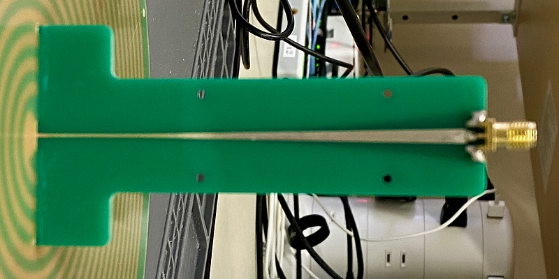
Microstrip antenna
I made a microstrip antenna during my graduation research in my fourth year of university. This is one of the antennas at that time.
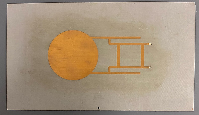
This is an antenna receives RHCP radiowaves using a turnstile configuration. It has a ladder type hybrid circuit that creates a 90 degree phase difference, and the two outputs are connected to two locations on the patch section separated by 90 degrees. The impedance at resonance at the edge of the patch was calculated to be 370 ohms, so I added a stub to match the impedance to 50 ohms. Before that, I prototyped a single-point feeding antenna, but the radiowave radiation from the stub was large. Therefore, I couldn’t expect this antenna to have good directivity characteristics, but I thought I’d try experimenting with circular polarization. I was aiming to receive GPS radiowaves with this antenna.
In fact, this antenna did not work as expected because the 50 ohm and 36 ohm wires that make up the ladder hybrid circuit were reversed. It was my mistake.
In addition to this, I had the opportunity to prototype many antennas, including a single-point-fed circularly polarized antenna using a degenerate separation element, and an antenna that utilizes higher-order modes, which was fun. To the people at Japan Antenna, who kindly provided materials and equipment for the students’ reckless and error-filled experiments, and who gave advice when we got stuck, allowing us to have a valuable experience. I would also like to design and manufacture antennas.
Conclusion
It’s been a while since I’ve fallen in love with antennas. I had to study again and learn new things, but it was fun.