Texas Instruments 60 GHz millimeter-wave radar evaluation kit experiment
Introduction
In recent years, millimeter-wave radar is often available as a safe driving option for private cars. In Japan, such a radar in the 76 GHz band is used.
In radar, the range resolution is determined by its frequency bandwidth. The range resolution of a radar with a bandwidth of 500 MHz is 30 cm. The wider the bandwidth available, the higher the range resolution and thus the smaller objects can be identified.
In June 2019, Texas Instruments announced a millimeter-wave radar evaluation kit (EVK: evaluation kit) with a bandwidth of 4 GHz in the frequency band of 60 GHz, so I tried it out. The range resolution is less than 4 cm, which is expected to facilitate human detection. In Japan, the use of 60 GHz wideband radar will be in examination. Google’s new Pixel 4 smartphone has a 60 GHz wideband radar named “Soli.”
IWR6832ISK + MMWAVEICBOOST
The evaluation kit used this time is the antenna plug-in module IWR6832ISK, carrier card platform MMWAVEICBOOST, and power supply card MMWAVEPOEEVM. MMWAVE is an abbreviation of milli-meter wave, IC is an acronym of integrated circuit, POE is a power supply over Ethernet (power over Ethernet), and EVM is for an evaluation module. There are several Antenna plug-in modules with different frequency bands and antenna types. The minimum configuration is a combination of IWR6832ISK and MMWAVEICBOOST, as described in Product Page.
What is amazing is its price. I purchased the above 3 boards, and the total cost was US $ 449.
On the other hand, documents such as User’s Guide contain only the minimum requirements. Also, looking at other official documents, I haven’t kept up with the post-release updates of this product.
Unpacking and power supply
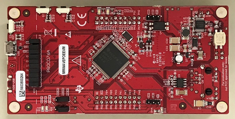
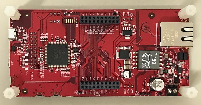
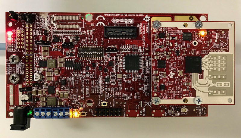
These photos are for the front and back of the radar common platform, MMWAVEICBOOST. This board is responsible for radar signal processing.
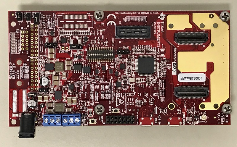
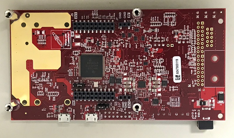
On the upper center of the surface is the high-density connector of the raw data recording board DCA1000. I connected the antenna plug-in module to the two high density connectors on the left side of the surface. The lower left DC jack is the power connector and the operating voltage is 5 volts. The current was about 370 milliamperes. The connection with the personal computer is made through the “XDS110 USB connector” located on the left side of the center of the back. It seems that power can be supplied using this USB connector by switching the front DIP switch.
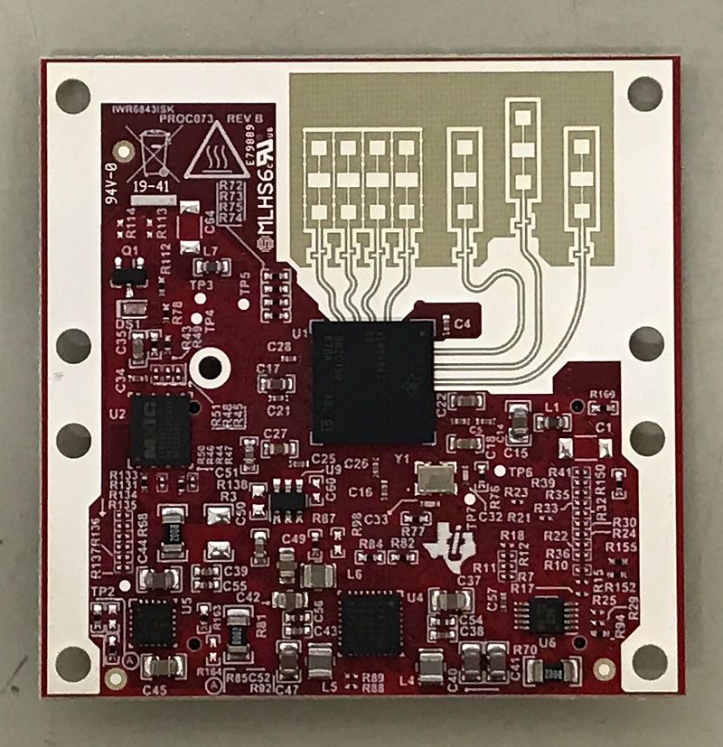
The photos are for the front and back of the IWR6832ISK antenna plug-in module. At the top of the surface is a beautiful 60 GHz microstrip antenna.
The left 4-branch antenna is the receiving antenna, and the right 3-branch antenna is the transmitting antenna. A radar that detects objects using multiple antennas for both transmission and reception is called MIMO (multiple-input multiple-output) radar and uses a new signal processing technology.
The microstrip antenna has a specific bandwidth (bandwidth with respect to the center frequency) of only a few percent, which is disadvantageous for use in a wideband radar, but it can radiate radio waves uniformly over a wide angle. Each antenna branch on this module consists of three microstrip antennas. The shapes of the central element of the microstrip antenna and the upper and lower elements are different. In addition, since the specific bandwidth of this radar exceeds 6%, the central element plays the role of the main antenna, and the upper and lower elements double as the array antenna that narrows the vertical beam width and the role of stagger tuning that widens the frequency bandwidth. I think the receive antenna branches are horizontally spaced at half wavelength intervals, while the transmit antenna branches are horizontally spaced at one wavelength interval, with the central antenna offset vertically. An impedance conversion transformer with a microstrip line is configured in the power feeding part of the element, and a stub is attached in front of it. A thin ground wire is used to separate the antenna branch. There must be a reason for the ground bump on the receiving antenna branch. The shape of the wiring bend (main liner) for equalizing the wiring length is also beautiful. I think it’s a very beautiful design.
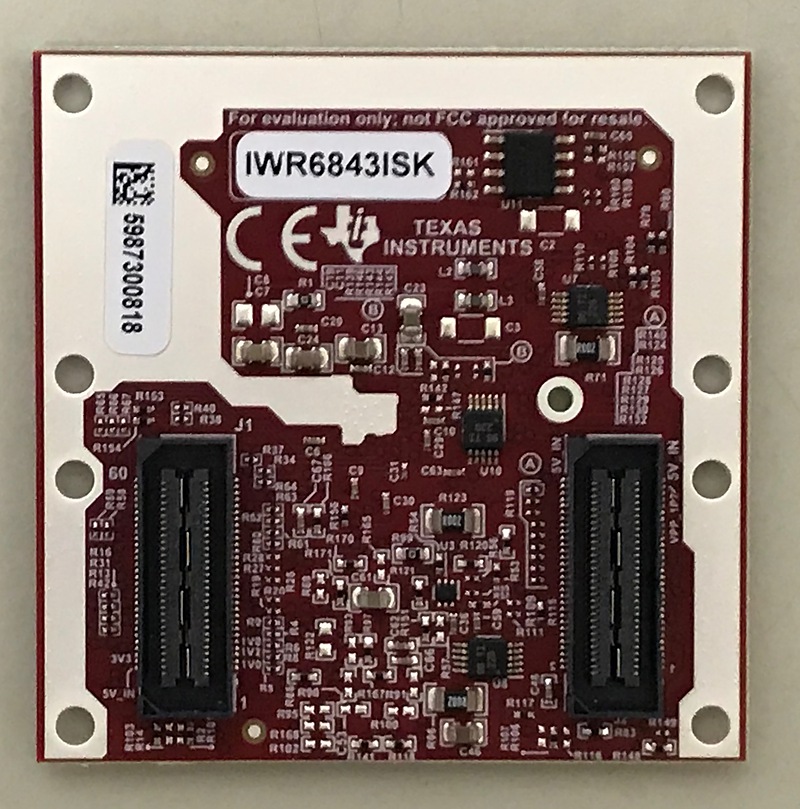
There is a high temperature danger mark on the left side of the antenna, but it was a temperature that could be touched by hand even during operation. On the back side of the board, there are two high-density connectors for connecting to the MMWAVEICBOOST board.
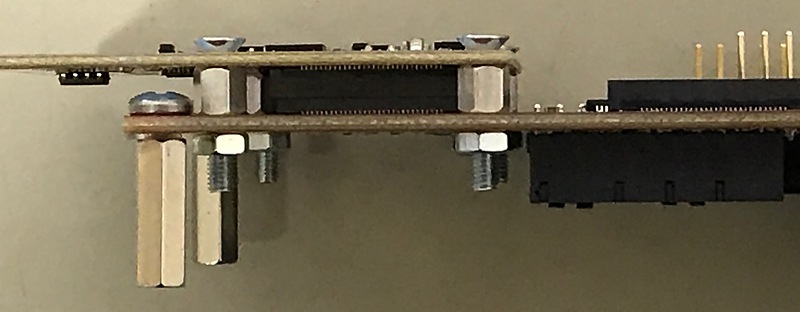
Connect this IWR6832ISK and MMWAVEICBOOST. According to the user’s manual, the two washers are used to match the height, but it was the spacer that was included in the kit. I fixed them using this spacer and successfully connected them.
Note that one of the nuts will come into contact with the components on the MMWAVEICBOOST board, so this nut must be installed carefully. This radar is such a wonderful product that I don’t mind this kind of error.
Next is the POE board MMWAVEPOEEVM. We can see the IC called MSP432E4 on the surface. This IC is not only POE but also USB emulation is possible. When these three boards are combined, it will be possible to use Ethernet from power supply to sensing, and it is possible to manage multiple radars from a single PC via a network.
In order to change the connection destination of the power supply and the XDS110 USB to the MMWAVEPOEEVM board, it is necessary to change the DIP switch on the MMWAVEICBOOST board. This MMWAVEPOEEVM can also be act as a web server by updating the firmware.
As a result of trial and error, I decided to give up using MMWAVEPOEEVM for the time being. I removed the MMWAVEPOEEVM board from the MMWAVEICBOOST board and returned the DIP switch settings to stand-alone.
Experiment
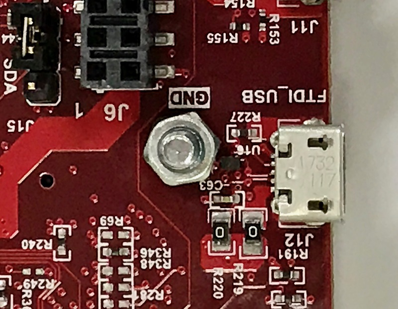
According to MMWAVEICBOOST’s User’s Guide, I installed the evaluation software MMWAVE-SDK and connect the PC to the XDS110 USB terminal on the MMWAVEICBOOST board.
The MMWAVEICBOOST User’s Guide states that both the XSD110 USB and FTDI USB should be connected to a computer. However, according to the MMWAVE-SDK User’s Guide, I cannot not find out why the FTDI USB terminal should be connected to the personal computer. So I tried both with and without the FTDI USB connected, but there was no change.
After the MMWAVE-SDK installation is complete, we should note the two XDS110 COM port numbers. In Windows 10 on the personal computer, type “devmgmt.msc” from the search window at the bottom to start the device manager, and find out “Port (COM and LPT)” and the COM numbers of “XDS110 Class Application/User UART” and “XDS 110 Class Auxiliary Data port.” When you connect the XDS110 USB to your computer, these two ports will appear. Please note that the Application/User UART numbers are not always lower than the Auxiliary UART numbers.
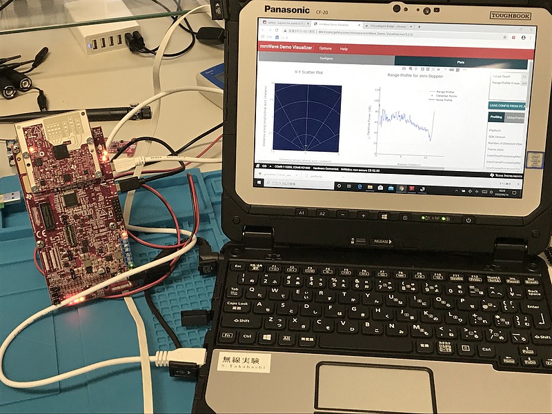
Next, I accessed mmWave Demo Visualizer using Chrome, an internet browser. This is a Chrome-only web application. There are also standalone applications. We can download the applications of Linux 64 bit, Mac and Windows at Download page. Usability was the same for web applications and standalone applications.

Then, point to “Options” “Serial Ports” of this application in order, and select the COM port of the previous Application/User for “CFG_PORT” and the COM port of the previous Auxiliary for “DATA_PORT”. Set Baud Rates to the default and press the OK button.
Next, select “xWR68xx” for Platform and “4Rx 3Tx” for Antenna Config in “Setup Details” of the Configure tab. You can change the signal processing parameters, but at first I used the default ones. Then pressed “SEND CONFIG TO MMWAVE DEVICE”. If many characters are displayed in Console Messages on the left side, it is successful. Go to the Plots tab.
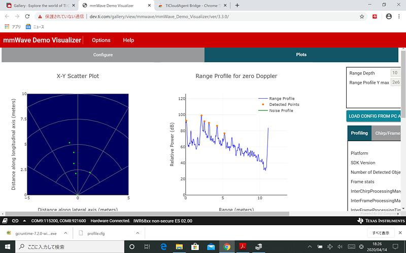
X-Y Scatter Plot and Range Profile for zero Doppler are displayed there. The performance of our anechoic chamber does not seem to be very good and in this example 6 targets are displayed. X-Y Scatter Plot…, yes, we can see objects are on the left or right. I think that the radar system is FM-CW (frequency modulation, continuous wave) that scans the entire 4 GHz bandwidth. Results are updated in near real time. it’s great.
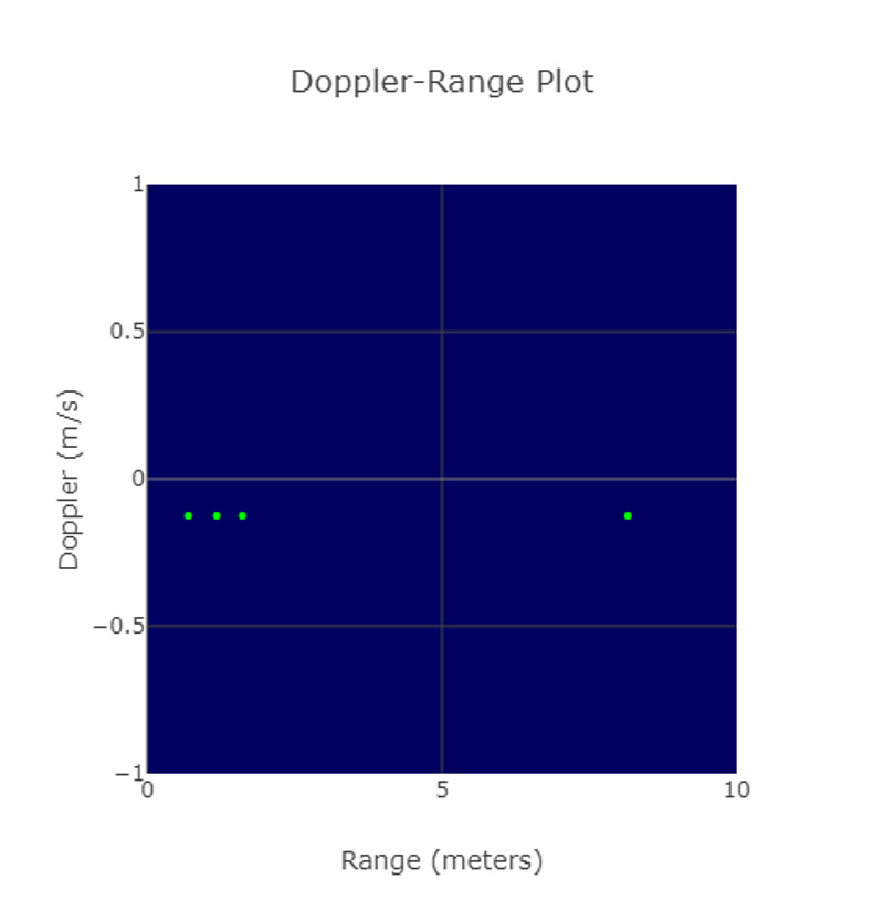
When the antenna is moved, the target moves relatively, and the Doppler effect causes a frequency change in the received reflected signal. The relative velocity of each object can be detected from the frequency change. In addition, it is a deep radar that can adjust CFAR (constant false alarm rate) parameters that determine the trade-off between target detection performance and noise malfunction.
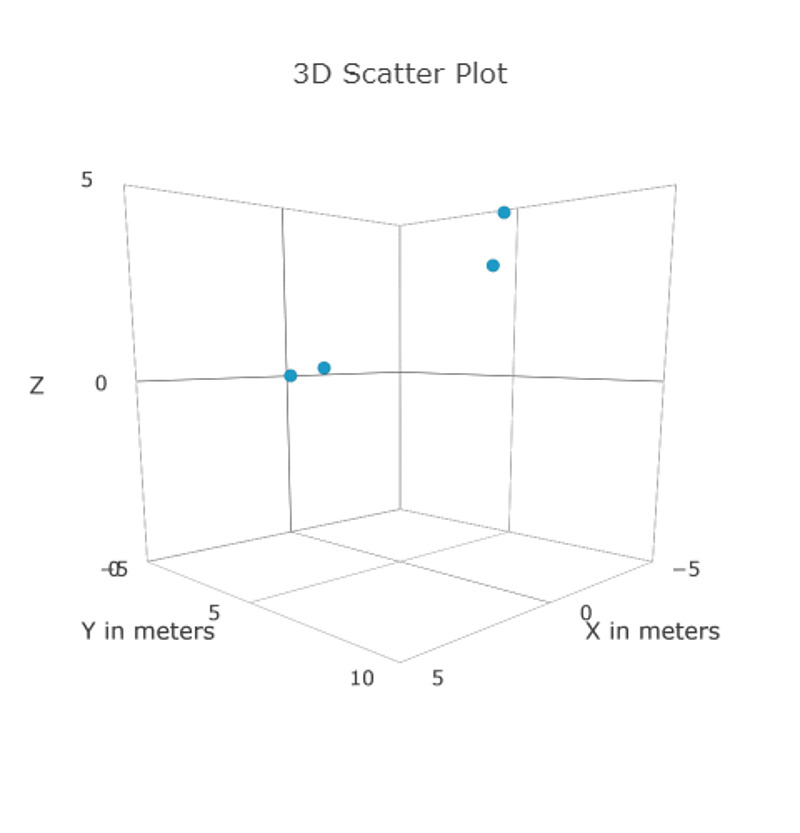
Three dimensional target detection was also possible because of the offset MIMO transmission antennas.
If the spread of coronavirus infection has subsided, I would like to use this radar for outdoor experiments.