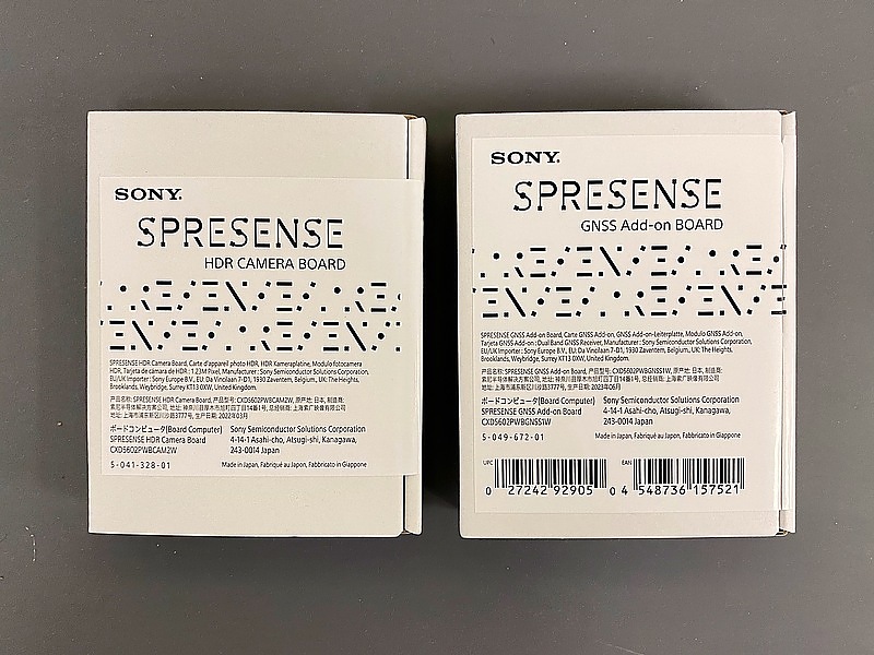
Add-on board for Sony Spresense -- GNSS receiver and HDR camera
Introduction
A new official add-on board for the board computer Spresense from Sony Semiconductor Solutions has been released. Multi-frequency GNSS (global navigation satellite system) receiver and HDR (high dynamic range) camera. I tried to run them on the Arduino IDE.
GNSS Addon Board
Spresense is a palm-sized microcomputer with features such as low power consumption, multi-core, built-in GNSS receiver, and audio playback. An add-on board is an additional function board that can be connected to the pin header on the top of the microcomputer.
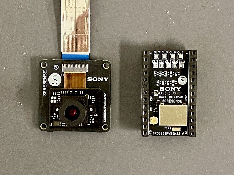
The GNSS add-on board has MRAM (Magnetoresistive memory, non-volatile memory with little rewriting deterioration), which seems to be used to speed up satellite acquisition when restarting. It is a great composition that achieves both low power consumption and high-speed satellite acquisition. The description on the official website says “Keep this board away from strong magnetism”, but this is more of a function than a drawback.
The CXD5610 GNSS receiver LSI has a built-in MRAM, so if you bring something that emits strong magnetism such as a magnet close to it, the data stored in the MRAM may be erased and it may not work properly.
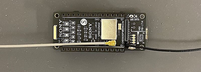
While the Spresense built-in GNSS receiver only receives L1 frequency band, this GNSS add-on board can receive both L1 and L5 band radio waves. While Spresense has a built-in GNSS antenna, this add-on board requires a separate antenna and has a U.FL connector for it.
GNSS antennas generally have a built-in low noise amplifier (LNA). In order to supply power to the LNA, the receiver is required to supply a DC voltage of 3 to 5 volts to the antenna terminal. The power supply to Spresense is 5 volts, but 3.3 volts is also used internally, and in order to achieve low power consumption, 1.8 volts is standard for the input and output terminals. Is power for LNA supplied to the antenna terminal of this add-on board?
I checked the GNSS add-on board schematic and found that the 3.3 volt power supply I found that it is supplied by the management IC, XC8109AC10BR-G. Also connected to the antenna terminal is a SAW (surface acousitc wave) filter that selects the L1 and L5 frequency bands.
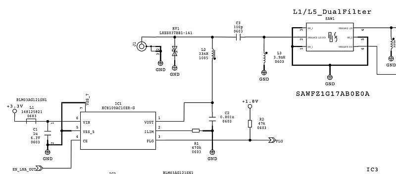
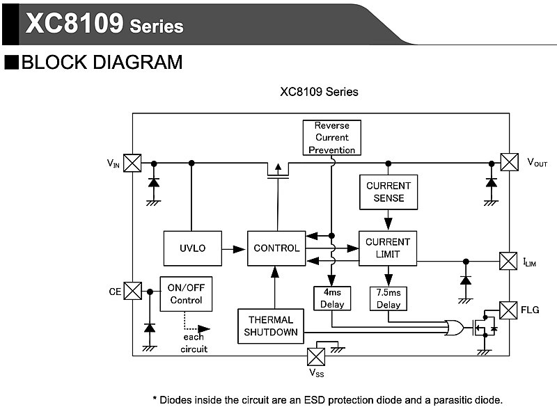
According to this XC8109 data sheet, this IC is a power supply control (CE: chip enable) from the microcomputer and an electrostatic breakdown prevention. (ESD: electrostatic discharge), it also has overcurrent blocking, reverse current prevention, and high temperature shutdown functions, and also has FLG (flag) output to notify the microcomputer of the status. This is also a great composition.
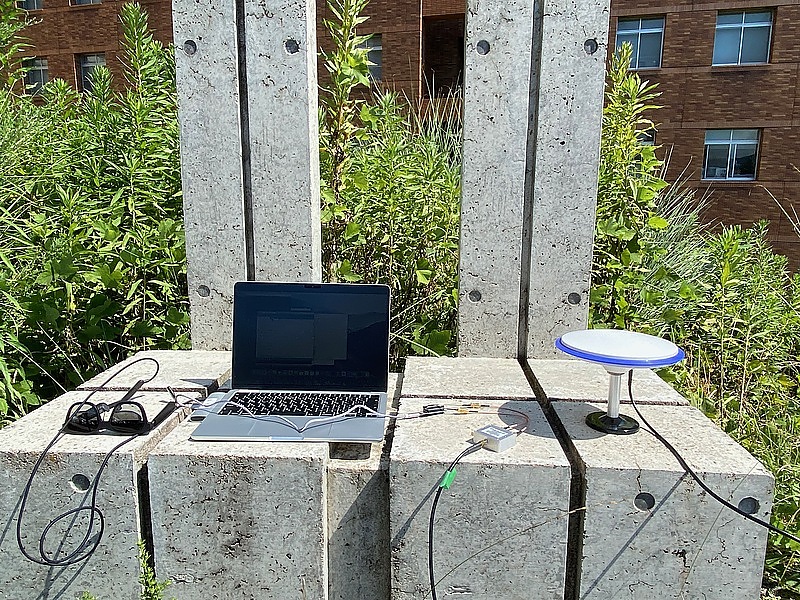
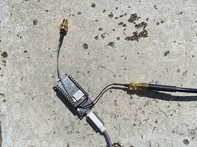
I have modified the Spresene mainboard to connect an external antenna. I connected the GNSS add-on board to this and compared the built-in GNSS receiver and the add-on board GNSS receiver using the same external antenna. The antenna used here is the Beitian BT-200, which can handle multiple frequencies.
First, I connected the main board antenna terminal and the add-on board antenna terminal to a two-way splitter. When I connected the antenna terminal of the add-on board to the current passing terminal of the splitter, the main board GNSS did not work. When the add-on board was not used, power was not supplied to the antenna terminal, so the main board GNSS function did not work. This can be said to be an operation for low power consumption. Since the mainboard antenna terminal always supplies LNA power, connecting this to the current passing terminal of the splitter would be perfect.
Here, the GNSS antenna was alternatively connected to the main board antenna terminal and the add-on board antenna terminal. The software is gnss_addon.ino. When using the main board, set the class name to SpGnss, and when using the add-on board, set the class name to SpGnssAddon. This class design provides the convenience of using the same software on the main board and add-on boards.
The log when using the GNSS function of the main board is as follows:
SpGnss : begin in
SpGnss : begin out
SpGnss : start in
  mode = HOT_START
SpGnss : start out
Gnss setup OK
1980/01/06 00:00:03.000615, numSat: 0, No-Fix, No Position
1980/01/06 00:00:04.000657, numSat: 6, No-Fix, No Position
1980/01/06 00:00:05.000658, numSat: 6, No-Fix, No Position
1980/01/06 00:00:06.000656, numSat: 7, No-Fix, No Position
1980/01/06 00:00:07.000648, numSat: 7, No-Fix, No Position
1980/01/06 00:00:08.000649, numSat: 6, No-Fix, No Position
1980/01/06 00:00:09.000646, numSat: 6, No-Fix, No Position
1980/01/06 00:00:10.000646, numSat: 6, No-Fix, No Position
1980/01/06 00:00:11.000645, numSat: 7, No-Fix, No Position
1980/01/06 00:00:12.000645, numSat: 7, No-Fix, No Position
1980/01/06 00:00:13.000644, numSat: 7, No-Fix, No Position
1980/01/06 00:00:14.000643, numSat: 7, No-Fix, No Position
1980/01/06 00:00:15.000643, numSat: 7, No-Fix, No Position
1980/01/06 00:00:16.000642, numSat: 8, No-Fix, No Position
1980/01/06 00:00:17.000642, numSat: 8, No-Fix, No Position
1980/01/06 00:00:18.000641, numSat: 7, No-Fix, No Position
1980/01/06 00:00:19.000642, numSat: 7, No-Fix, No Position
1980/01/06 00:00:20.000640, numSat: 7, No-Fix, No Position
1980/01/06 00:00:21.000639, numSat: 9, No-Fix, No Position
1980/01/06 00:00:22.000638, numSat:10, No-Fix, No Position
1980/01/06 00:00:23.000638, numSat: 9, No-Fix, No Position
1980/01/06 00:00:24.000637, numSat: 8, No-Fix, No Position
1980/01/06 00:00:25.000636, numSat:10, No-Fix, No Position
1980/01/06 00:00:26.000641, numSat:10, No-Fix, No Position
1980/01/06 00:00:27.000641, numSat: 8, No-Fix, No Position
1980/01/06 00:00:28.000638, numSat: 8, No-Fix, No Position
1980/01/06 00:00:29.000634, numSat: 8, No-Fix, No Position
1980/01/06 00:00:30.000633, numSat: 8, No-Fix, No Position
1980/01/06 00:00:31.000632, numSat: 8, No-Fix, No Position
1980/01/06 00:00:32.000632, numSat: 7, No-Fix, No Position
1980/01/06 00:00:33.000631, numSat: 9, No-Fix, No Position
1980/01/06 00:00:34.000633, numSat: 9, No-Fix, No Position
1980/01/06 00:00:35.000630, numSat: 7, No-Fix, No Position
1980/01/06 00:00:36.000629, numSat: 7, No-Fix, No Position
1980/01/06 00:00:37.000627, numSat: 7, No-Fix, No Position
1980/01/06 00:00:38.000628, numSat: 7, No-Fix, No Position
1980/01/06 00:00:39.000630, numSat: 7, No-Fix, No Position
1980/01/06 00:00:40.000627, numSat: 7, No-Fix, No Position
1980/01/06 00:00:41.000626, numSat: 7, No-Fix, No Position
1980/01/06 00:00:42.000627, numSat: 7, No-Fix, No Position
1980/01/06 00:00:43.000632, numSat: 8, No-Fix, No Position
1980/01/06 00:00:44.000624, numSat: 8, No-Fix, No Position
1980/01/06 00:00:45.000623, numSat: 8, No-Fix, No Position
2023/08/01 05:40:26.000652, numSat: 8, No-Fix, No Position
2023/08/01 05:40:26.795351, numSat: 8, Fix, Lat=34.440642, Lon=132.415095
2023/08/01 05:40:27.000707, numSat: 8, Fix, Lat=34.440642, Lon=132.415095
On the other hand, the log when using the add-on board is as follows:
SpGnss : begin in
SpGnss : begin out
SpGnss : start in
  mode = HOT_START
SpGnss : start out
Gnss setup OK
2000/01/02 00:00:03.000000, numSat:14, No-Fix, No Position
2000/01/04 05:35:02.000000, numSat:18, No-Fix, No Position
2000/01/04 05:35:03.000000, numSat:20, No-Fix, No Position
2000/01/04 05:35:04.000000, numSat:20, No-Fix, No Position
2000/01/04 05:35:05.000000, numSat:20, No-Fix, No Position
2000/01/04 05:35:06.000000, numSat:20, No-Fix, No Position
2000/01/04 05:35:07.000000, numSat:20, No-Fix, No Position
2000/01/04 05:35:08.000000, numSat:20, No-Fix, No Position
2000/01/04 05:35:09.000000, numSat:19, No-Fix, No Position
2000/01/04 05:35:10.000000, numSat:19, No-Fix, No Position
2000/01/04 05:35:11.000000, numSat:21, No-Fix, No Position
2000/01/04 05:35:12.000000, numSat:22, No-Fix, No Position
2000/01/04 05:35:13.000000, numSat:24, No-Fix, No Position
2023/08/01 05:35:14.000000, numSat:24, No-Fix, No Position
2023/08/01 05:35:15.000000, numSat:24, No-Fix, No Position
2023/08/01 05:35:16.000000, numSat:24, No-Fix, No Position
2023/08/01 05:35:17.000000, numSat:24, No-Fix, No Position
2023/08/01 05:35:18.000000, numSat:24, No-Fix, No Position
2023/08/01 05:35:19.000000, numSat:24, No-Fix, No Position
2023/08/01 05:35:20.000000, numSat:24, No-Fix, No Position
2023/08/01 05:35:21.000000, numSat:24, No-Fix, No Position
2023/08/01 05:35:22.000000, numSat:24, No-Fix, No Position
2023/08/01 05:35:23.000000, numSat:24, No-Fix, No Position
2023/08/01 05:35:24.000000, numSat:24, No-Fix, No Position
2023/08/01 05:35:25.000000, numSat:24, No-Fix, No Position
2023/08/01 05:35:26.000000, numSat:24, No-Fix, No Position
2023/08/01 05:35:27.000000, numSat:24, No-Fix, No Position
2023/08/01 05:35:28.000000, numSat:24, No-Fix, No Position
2023/08/01 05:35:29.000000, numSat:24, No-Fix, No Position
2023/08/01 05:35:30.230000, numSat:24, Fix, Lat=34.440652, Lon=132.415128
2023/08/01 05:35:31.000000, numSat:24, Fix, Lat=34.440629, Lon=132.415111
The GNSS add-on board was able to position in less time than the main board was.
HDR Camera Addon
This HDR camera has an FPGA and can also encode to JPEG. It’s amazing.
The Spresense HDR camera board is equipped with an FPGA and a color space conversion circuit and a JPEG encoder, so in addition to Y/Cb/Cr, RGB and JPEG format images can be sent to Spresense.
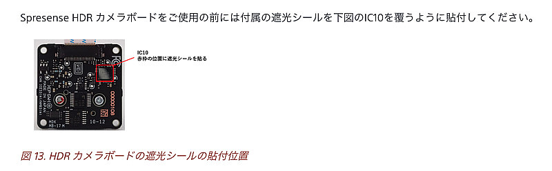
Before using the HDR camera add-on board, some ICs must be covered with light shielding tape, just like the Spresense main board. This tape was attached to the back of the cardboard that held the housing together. Be careful not to throw away the cardboard before applying this tape.
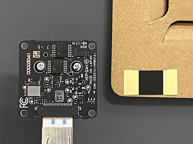
Paste this light shielding tape on the add-on board IC.
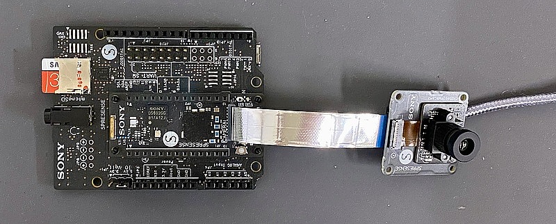
After that, insert the flat cable terminal of the add-on board into the Spresense main unit. There is no special cable retention mechanism on the camera connector side of the main board. The software used is camera.ino. This sample code records JPEG files on the SD card, so an expansion board is required in addition to the main board.
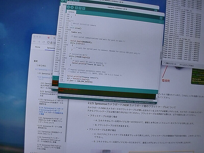
I didn’t have a suitable subject, so I tried to project my PC display. I would like to use this HDR camera to shoot various things outdoors.
Conclusion
I tried the GNSS add-on board for Sony Spresense and the HDR camera board. I have the impression that the GNSS add-on board is very carefully made. The HDR camera add-on board is also highly functional. Both aim to achieve both low power consumption and high functionality. I will enjoy using them.
I would like to find subjects that make use of the features of this HDR camera and enjoy the GNSS add-on board.