Attaching GNSS external antenna connector to Sony Spresense
Sony’s one-board microcomputer, Spresense, is equipped with a GNSS antenna on the microcomputer board. It can receive the disaster/crisis report signals and the submeter augmentation signal from QZS (Quasi-Zenith Satellite), as well as the positioning signals of GPS (Global Positioning System) and QZS. Furthermore, from v.2.0.0 update on June 12, 2020, it is possible to decode satellite signals from Galileo of European satellite and BeiDou in Chinese satellite, and it can output 1-PPS (pulse-per-second) signals to a GPIO (general purpose input/output) pin. Sprsense is evolving day by day and I’m always looking forward to the release notes.
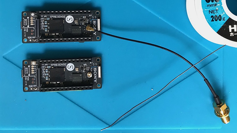
I have installed this Spresense outdoors to continuously observe QZS’s disaster/crisis management report signals. For more stable reception, I attached an external antenna terminal on the Spresense.
Instructions on how to attach an external antenna connector to Spresense can be found in Section 1.18.2 of Hardware Guide. To use an external active antenna, remove one zero ohm chip resistor, make a jumper connection at one location, and attach a board mount technology (SMT) u.FL connector. This resistance size is called 1005 size and is 0.5 mm wide and 1 mm long. The part that looks like a small silver dot near the center of the photo above is this removed chip resistor. In order to attach an external GNSS antenna terminal to Spresense, such detailed work is required.
I enlarged the above explanation page and check the resistance to be removed and the board position to jumper.
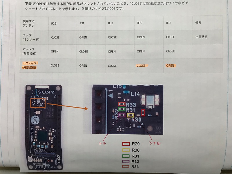
First, I removed the resistor R31. Using an 18-watt soldering iron and fine-tipped tweezers, I applied the soldering iron to one side of the resistor for about 3 seconds, and then I was able to remove it.
Next, I short-circuited the part of R30. Cut the tin-plated wire short to a chip resistance of about 1005 size, lightly put solder on the board land of this R30, and solder this tin-plated wire while holding it with tweezers. This tin-plated wire was attached to the soldering iron, and sometimes this plated wire was attached to another place. With the image of leaving the tin-plated wire and escaping, it was tenacious and soldered.
Then I attached the u.FL connector to Spresense. After solder-plating the connector terminal part and the Spresense mounting part, while pressing the connector against the Spresense board with tweezers, soldering was done by applying a soldering iron to the side of the connector body and indirectly applying heat. After that, I confirmed that the u.FL connector did not wobble. It was difficult to adjust the amount of solder to put on the u.FL connector, and I consumed 4 u.FL connectors including failure to install the GNSS connector on 2 Spresense.
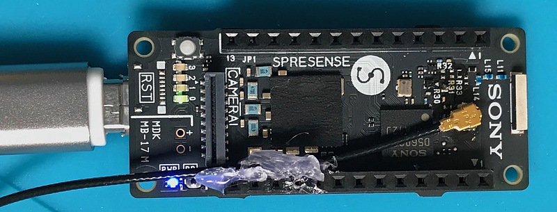
Finally, check the continuity and operation. Make sure that the u.FL connector ground and the board ground (for example, the land of the screw mounting part) are conductive, and that the u.FL connector ground and the center are not conductive. Make sure that this u.FL connector is not short-circuited, then power Spresense and check the connection of the center pin of the u.FL connector. If there is a potential difference of 3.3 volts between the u.FL connector center and ground, the GNSS connector installation is successful. The coaxial cable connected to the u.FL connector was fixed with a glue gun so that no extra force was applied to the u.FL connector.
Even though I have presbyopia and I had a hard time, I was able to attach an external antenna connector to Spresense. According to the information on CXD5602, the core chip of Spresense, the GNSS reception processor of is [independent] from the application processor. I would like to try utilizing power management, sensor management functions, and multi-core of Spresense.