TCXO replacement for ADALM-PLUTO (PlutoSDR)
Introduction
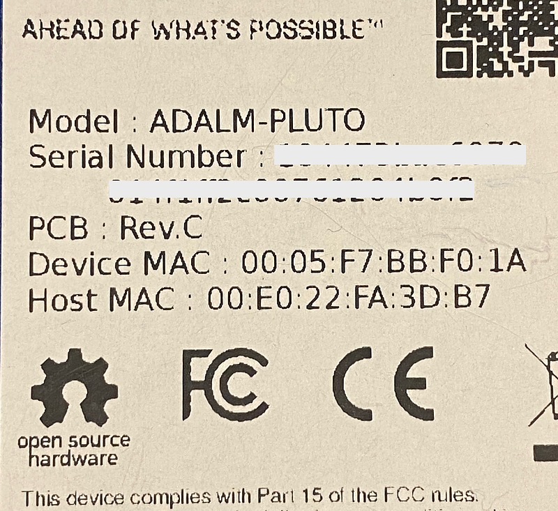
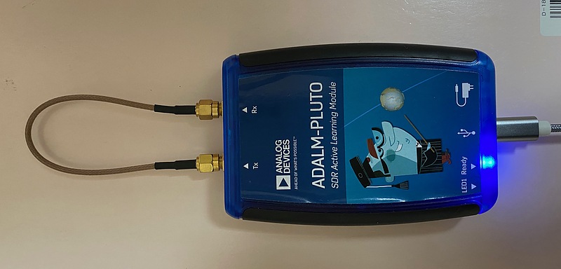
ADALM-PLUTO (aka PlutoSDR) is a software defined radio (SDR) hardware from Analog Devices.
Looking at the article “Modification of PlutoSDR” written by Professor Takuji Ebinuma of Chubu University, I want to replace TCXO (temperature compensated crystal oscillator) with stable one. This TCXO replacement improves the frequency stability from 25 ppm to 0.5 ppm, and it seems that PlutoSDR can be widely used for such as navigation receivers.
I also added connectors for the 2nd transmission and reception channel.
Revision C vs. Revision D
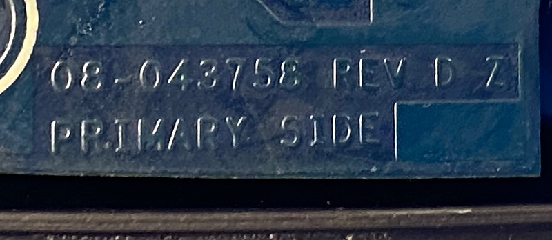
The revision D of PlutoSDR is on sale now. According to PlutoSDR’s hardware description, revision C has not been released and revisions C and D are almost identical. The label on my PlutoSDR PCB indicates the revision is D.
However, the revision written on the PlutoSDR case seal was C. I was told that there is no difference between revision C and D, so I didn’t care.
TXCO replacement
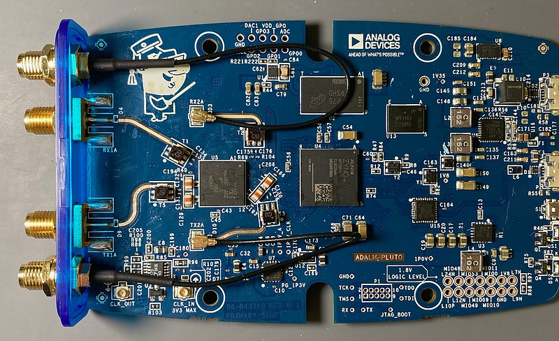
As the TCXO to be replaced, I used Epson Timing’s TG2520SMN mentioned in the article by Professor Ebinuma. Unscrew the PlutoSDR, and we can remove the TCXO labeled Y3 on the printed circuit board. It seems that there is a method of removing them with two soldering irons, but I used low temperature solder (surface mount component removal kit, SMD-21) and one soldering iron to remove it.
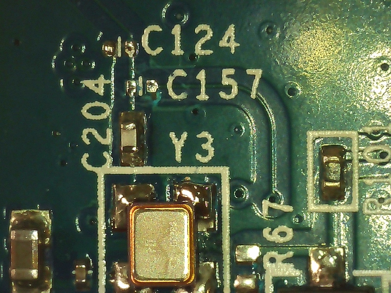
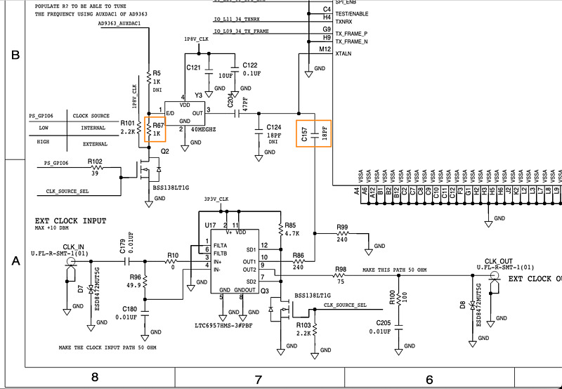
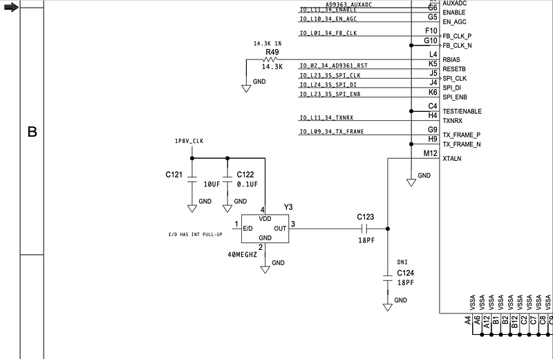
I also removed R67 and C157, just like Professor Ebinuma did. The solder did not melt even when a soldering iron was applied to the entire chip. Therefore, low-temperature solder was used for these removals as well. There is a C124 mark next to the C157 mark, but the parts were not attached. This C157 was easy to remove because C124 has no parts. PlutoSDR Rev.D circuit diagram 7 page lower left, C124 is It looks like you can do without it.
2-input 2-output (MIMO: multiple-input multiple output)
This revision D print circuit board is populated with extensions to 2 inputs and 2 outputs and their u.FL connectors. Therefore, I made holes for the additional connectors in the case and attached a u.FL-SMA conversion cable. YouTube: Enable Dual Receive and Dual Transmit for the new revision of Pluto
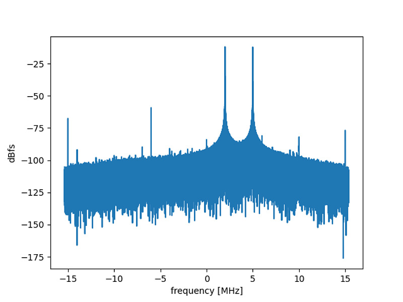
I tried Professor Ebinuma’s article “Modified version PlutoSDR operation test”. I connected TX1 and RX1 terminals, TX2 and RX2 terminals. Then I executed the loopback code that sent 2 MHz signal from TX1 and 5 MHz signal from TX2 and that received the both signals. My PlutoSDR also showed peaks at 2 MHz and 5 MHz, and the TXCO replacement and the MIMO modification were successful.
We can find the statement in the PlutoSDR revision D hardware description page:
The 2nd Rx/Tx channel internal to the rev D is not test during production test. If it works - bonus! If it doesn’t work; Pluto is only advertised as a 1 Rx, 1 Tx radio, and that is guaranteed/production tested on each unit - and that is what you received.
I am lucky and I will enjoy this PlutoSDR.
PlutoSDR revision B
I also have revision B of PlutoSDR. Comparing it with schematic (bottom left of page 7) around TXCOY3, the schematic of revision B is simple, and the pin 1 of Y3 is open.
When I compared the revision B bill of materials with the revision D bill of materials, the same parts were used for Y3. It seems that the TCXO in PlutoSDR revision B can be replaced with the more stable TCXO TG2520SMN.
(Added 2022-12-27)
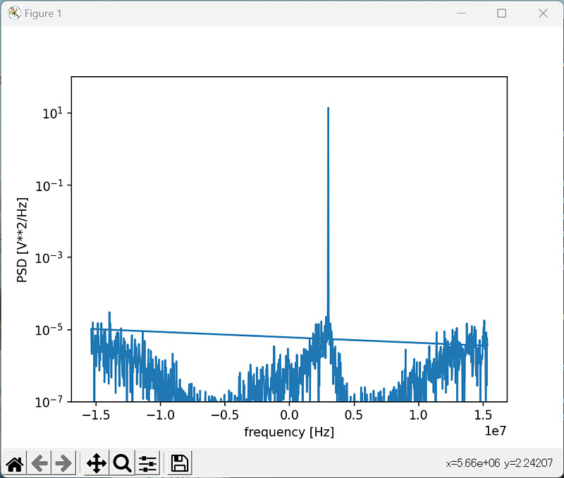
I have also successfully replaced the TCXO on my revision B PlutoSDR. I connected TX and RX and ran this source code.
The 3 MHz signal sent from the TX terminal is received at the RX terminal.
Related article(s):
- ADALM-PLUTO (PlutoSDR) Revision C 14th September 2022