Battery charging with BQ25890, a Texas Instruments' IC
If a lithium-ion battery charger can be controlled by a microcomputer, these battery can be used for a longer power cycles with a gentle charging method, whereas we can quickly charge them when the power supply is expected to be interrupted.
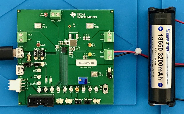
In this time, I used the Evaluation kit of Texas Instruments’ BQ25890, which can control charging parameters to charge and discharge the lithium ion battery. In addition, this IC can output power at a constant voltage while charging when the power is connected and when the battery needs to be charged. Whereas, it can continue to output power at the constant voltage from the battery when the external power is cut off.
This evaluation kit communicates with PCs by an I2C communication interface as the evaluation kit of battery remaining capacity estimation IC used in the previous experiment.
The dedicated I2C-USB serial converter, EV2300, for this evaluation kit is sold separately. In this time, I used the IC without any modifications in this experiment. In the future, I will modify default setting with I2C communication.
This evaluation kit has a terminal that allows the wire to be connected. Therefore, we can use it without worrying about wiring short-circuits. Since there are test pins on this kit board, we can easily connect them to microcomputers and measuring instruments. However, the function of each of them is somewhat difficult to understand.
External power supply is provided by the micro USB terminal marked as J5 or the VBUS terminal. The input voltage is ranging from 3.9 V to 14 V, and the quick charging is also possible. However, according to the circuit diagram, the voltage of the micro USB terminal for power input is directly output to the micro USB terminal for power output marked J6 next to it. At this time, I supplied the power to the J5 terminal with a USB charger. When power was supplied, the status LED (STAT, D3) on the evaluation kit board blinked rapidly.
I connected the lithium-ion battery to the BAT terminal. When a lithium ion battery was connected while power was being supplied, the status display LED changed from blinking to steady. The charging voltage was 4.1 V. Also, the current at the power supply terminal increased from 30 mA to 450 mA.
The output was provided to the SYS terminal. The voltage was around 4 V. It is difficult to drive various microcomputers as it is. However, there is the boost mode, and it seemed that 5 V output was also possible. For that purpose, it seemed that I should turn on this function by setting the fifth bit of register 03 to 1 by I2C communication and open the OTG (USB On-The-Go) terminal of JP6 which is the initial state. I will try it someday.
Another output is the PMD terminal. It seemed that it appeared the voltage as same as one of the external power when the external power was supplied and the voltage as same as one of the lithium-ion battery when the external power was not connected.
Lithium-ion batteries should be charged at the temperature ranging 10 to 45 degrees Celsius in principle. However, according to the guideline provided by JEITA (Japan Electronics and Information Technology Industries Association) on April 20, 2007, the lithium-ion battery can be used safely over a wider temperature range. For the temperature ranging 0 to 10 degrees Celsius, the charging current should be halved. On the other hand, the charging voltage should be decreased by 200 mV where the temperature is between 45 and 60 degrees Celsius. I would like to try turning on to the JEITA mode by entering the command with I2C communication.