Introduction of GNSS receiver NovAtel OEM729
High performance GNSS receiver OEM729
I introduced OEM729 receiver from NovAtel, a manufacturer of GNSS (global satellite navigation system) receivers in Canada.
In order to use OEM729, a development board is required in addition to the main body receiver board. This is to supply the multiple voltage power supply required for the operation of the receiver board, and to enable the receiver and personal computer to be connected via USB or Ethernet. I bought a third party as this development board. It’s strange that this development board can be connected not only to NovAtel OEM729, but also to other GNSS receiver manufacturer boards such as Trimble BD982. It seems that the pin arrangements among receiver manufacturers are common to some extent.
Equipment setup
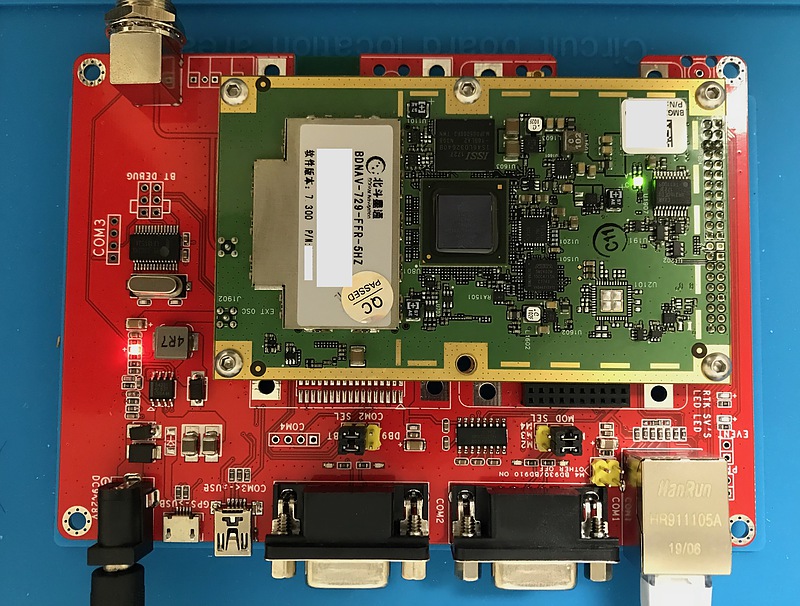
I ordered the receiver board and the development board from different stores at the same time, but the development board arrived first. I ordered a single development board, but I should have kept the development board with a case. Anyway, I took a lot of pictures because of the expectation of my first high-performance GNSS receiver. This is the surface of the development board that arrived earlier.
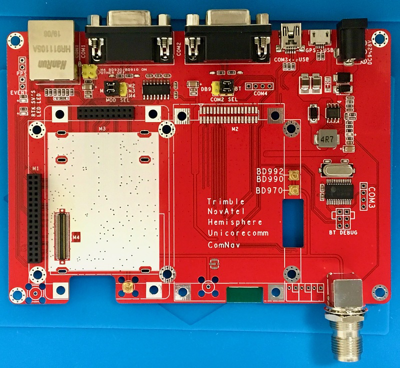
A layout change was announced on this development board, but it arrived on the old board. The position of the RS-232-C connector differs between the old and new boards. The COM1 and COM2 ports are output to the DSUB 25-pin connector, and the COM3 port is connected to the USB micro connector. Also, on this old board, SMB connectors were removed for each of the multiple GNSS receiver boards, and these signal lines were connected in parallel to the TNC connector that connects to the antenna. Looking at the product photo, it seems that the new board does not have a TNC connector to connect to the antenna, and a cable to convert from the SMB connector on the GNSS receiver board to the TNC connector is included. The new board is better in terms of impedance matching.
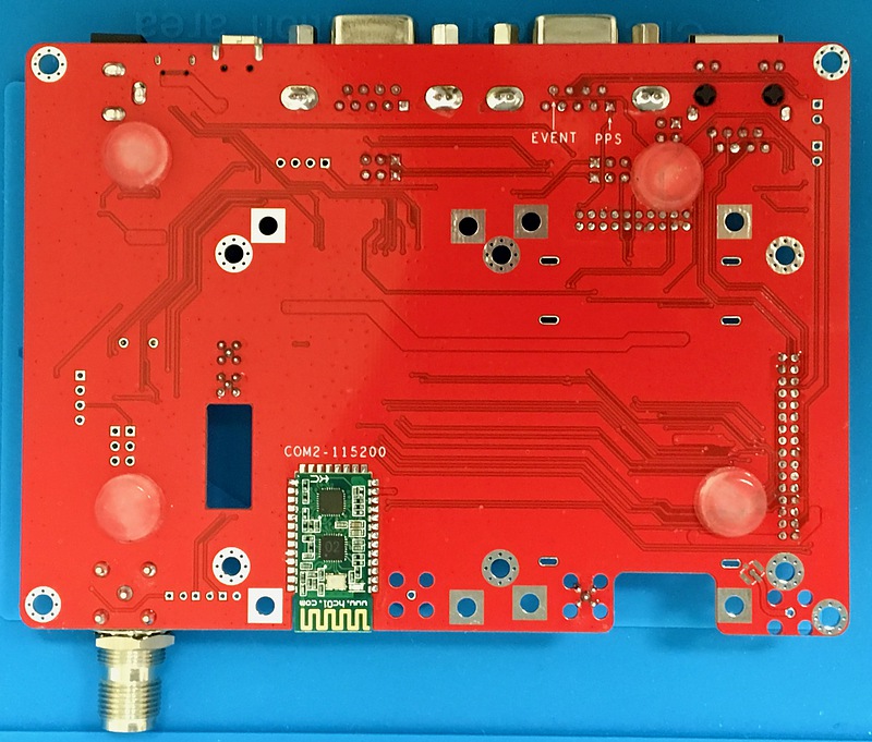
There was a Bluetooth sub-board on the back of the development board. There was a jumper pin on the board so that the COM2 port could be selected from the DSUB 25-pin connector and Bluetooth. By default, the COM2 port was connected to Bluetooth.
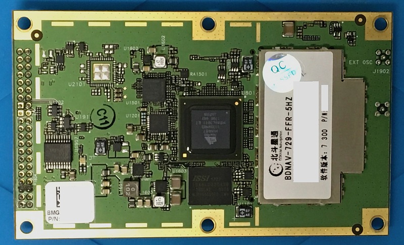
This is the surface of the NovAtel OEM729 receiver board that arrived after a while. You can see the NovAtel chip in the center and the letters BDNAV-729-FFR-5HZ, which is the model number of this receiver, on the right side. It seems that the positioning output can output 5 data per second.
On the back of the OEM729 receiver, there is a sticker that was written as Hardware Revision 2.1.
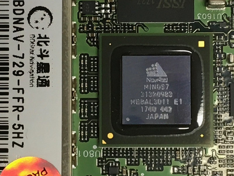
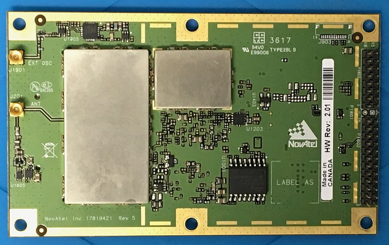
You can see the NovAtel MINOS 7 logo on the chip in the center of the photo. It was made in Japan.
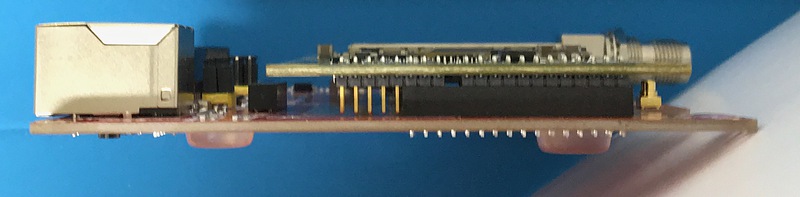
This is a photograph taken from the side by connecting the receiver board and the development board. Some of the pins on the receiver board were not connected to the development board. This development board included a spacer for connecting to the receiver base board and a hexagon wrench screw.
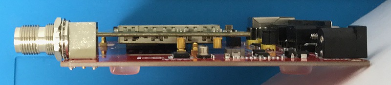
This is the antenna part. The antenna SMB connector of the receiver and the SMB connector of the development board are just right. The other SMB connector on the receiver board was for supplying an external clock signal, but it was not connected to this development board.
Power is supplied to this development board with the barrel jack at the bottom left of the photo. This input voltage range is 9 to 28 volts. In addition, this development board included an adapter that outputs 12 volt DC from a commercial power supply, so that you can immediately enjoy GNSS reception. The computer and this development board are connected through the microUSB port just to the left of this power barrel jack. When you install the driver software on your computer and connect it to this development board, you will see three ports on your computer named USB1, USB2, and USB3. Since it handles multiple communication ports, it is necessary to install special USB driver software.
Receiver settings
I downloaded Windows USB Driver version 5.0.1 and NovAtel Connect version 2.3.2, GUI (graphics user interface) software, from the NovAtel download page and installed them on my Windows PC. I also download the web interface firmware OEM7 WebUI version 2.6.1, the receiver firmware 7.07.03, and the PDF file of the OEM7 Command Logs Manual on another page. In particular, this OEM7 Command Logs Manual is a masterpiece with a total of 1,055 pages, but you will need to download it because you will be searching for the commands required for later settings using full-text search.
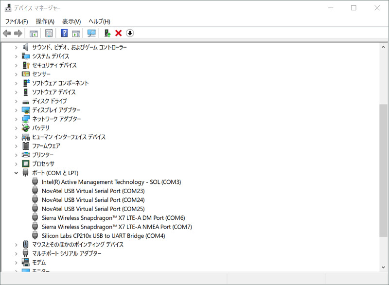
After connecting the development board to a Windows 10 PC with the USB driver software installed, I typed devmgmt.msc from the search window to launch Device Manager. The USB serial port numbers that appear here (here COM21, COM24, COM25) will be needed in the future, so I made a note of them.
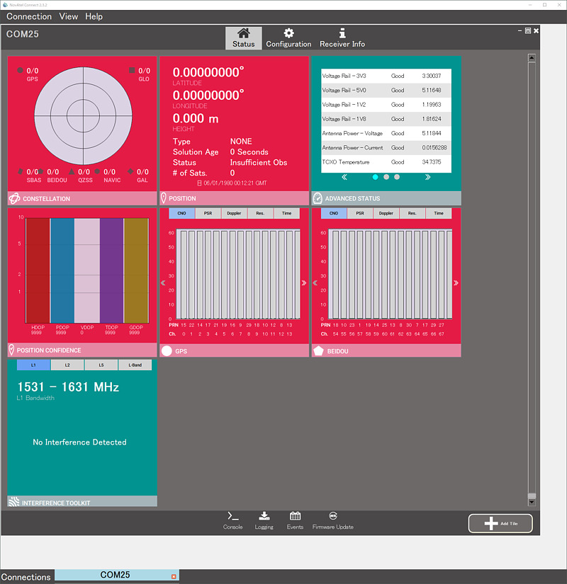
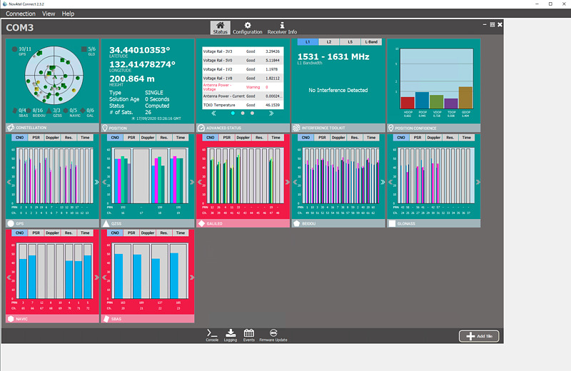
When I started NovAtel Connect and selected COM21, which is one of the above ports, the initial screen appeared. The antenna on the windowsill of my laboratory on the bottom floor of the university could not receive the GNSS satellite. Low-cost GNSS receivers can often receive about two satellite signals, but rather, high-performance GNSS receivers do not seem to be able to receive them.
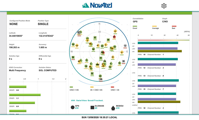
Double-click the NovAtel Connect tile to see its details. When I installed the receiver on the roof and double-clicked on the satellite constellation tile, I was able to observe many satellite signals.
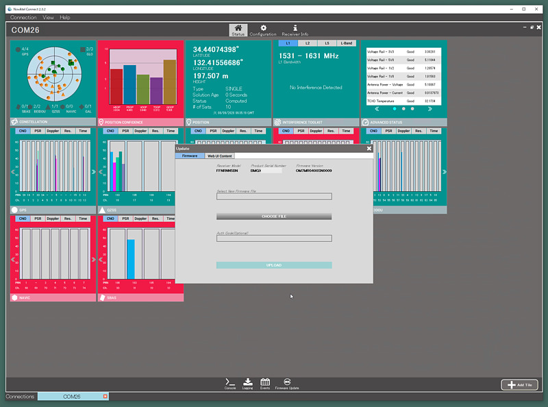
The firmware of the receiver and web interface can be updated from the Firmware Update button of NovAtel Connect. I downloaded the receiver firmware file 7.07-03-OEM.zip from NovAtel’s support page and updated the main unit firmware using OM7MR0703RN0000.shex in it. The old version is OM7MR0400SN0009 and the new version is OM7MR0703RN0000.
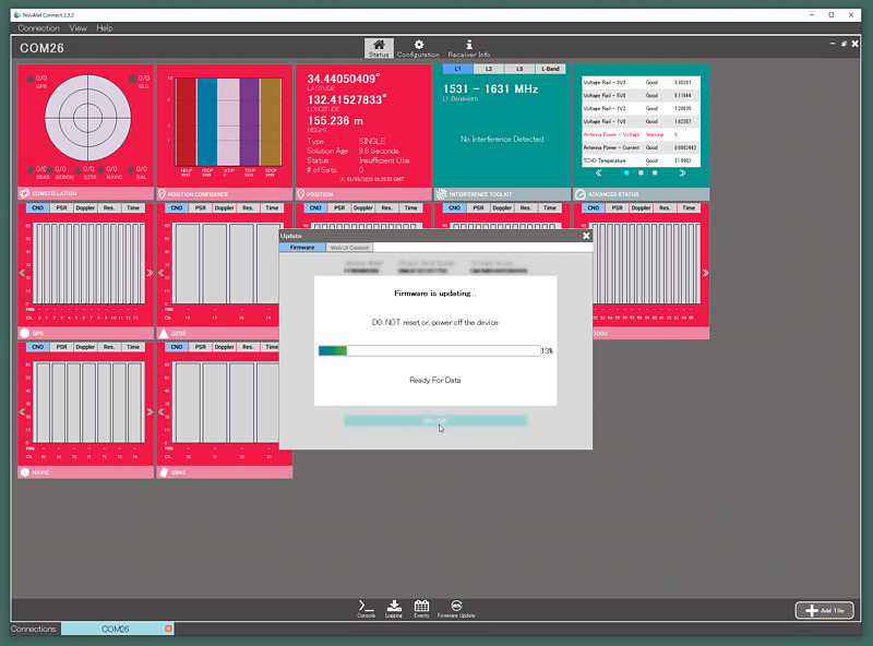
Firmware updates are always tense. I also downloaded the web interface firmware file WMC010206RN0001.zip and applied the firmware with the extension hex in it from Firmware Update.
Finally I was able to get the OEM729 receiver working.
Network interface settings
We will make further settings to make it easier to use. First, enable Ethernet. If Ethernet can be used, not only can we check the device status without using NovAtel Connect on your computer, but we can also remotely control it and send pseudo distances and almanac to NTRIP Caster.
Clicking Console under NovAtel Connect to open a console window and you will see the device serial number and firmware version.
<OK
[USB1]<VERSION USB1 0 56.5 FINESTEERING 2124 124438.519 02044048 3681 15823
<     3
<          GPSCARD "FFNRNN5BN" "xxxxxxxxxxxxxxx" "OEM729-2.01" "OM7MR0703RN0000" "OM7BR0002RB0000" "2019/Aug/12" "10:22:17"
<          OEM7FPGA "" "" "" "OMV070001RN0000" "" "" ""
<          DB_WWWISO "WWWISO" "0" "" "WMC010206RN0001" "" "2020/Jul/09" "13:15:54"
[USB1]
This information can also be viewed with the LOG VERSION command. The serial number part is hidden. Since the Ethernet interface is off by default, use the ETHCONFIG command to turn it on, and then save it with the SAVECONFIG command so that it will be reflected even after the power is turned on again. If successful, you will see the characters <OK and the prompt [USB1]. It seems to be case insensitive.
[USB1] ethconfig etha auto auto auto auto

<OK
[USB1] saveconfig

<OK
The IP address assigned by DHCP can be found from the DNS server log.
When the Ethernet interface is activated, the reception status of GNSS satellite signals can be displayed on the browser, and the receiver can be set. If you want to turn off the browser information display function, such as by connecting this receiver to the Internet without a firewall, set IPSERVICE WEB_SERVER DISABLE.
Display of reception function and setting of satellites used
In such high-performance GNSS receivers, it is common to reduce the number of types of hardware sold and instead allow us to set the functions available on the software by entering a character string called a key code. It is a method to upgrade the function with the release key such as sending by e-mail.
First, let’s explore the features that can be used with this receiver. Use commands that start with LOG to display information. The command to display the code of the function of this receiver is LOG AUTHCODE. Add A to the end of the command name to display a summary. Available features are represented by symbols such as MWP7W6.
[USB1] log authcodea once
<OK
#AUTHCODESA,USB1,0,59.0,FINESTEERING,2124,124751.000,02044048,2ad2,15823;VALID,1,SIGNATURE,TRUE,"MWP7W6,GC7PRH,47NKH7,GHPWC9,J55FP5,FFNRNN5BN"*8839ab39
Then use the LOG MODELFEATURES command to display these symbols as a highly readable string.
log modelfeatures once
<OK
[USB1]<MODELFEATURES USB1 0 68.0 FINESTEERING 2124 124976.706 02004048 141a 15823
<     21
<          5HZ MAX_MSR_RATE
<          5HZ MAX_POS_RATE
<          SINGLE ANTENNA
<          AUTHORIZED MEAS_OUTPUT
<          AUTHORIZED DGPS_TX
<          AUTHORIZED RTK_TX
<          AUTHORIZED RTK_FLOAT
<          AUTHORIZED RTK_FIXED
<          AUTHORIZED PPP
<          AUTHORIZED LOW_END_POSITIONING
<          AUTHORIZED RAIM
<          AUTHORIZED NTRIP
<          UNAUTHORIZED IMU
<          UNAUTHORIZED INS
<          UNAUTHORIZED ALIGN_HEADING
<          UNAUTHORIZED ALIGN_RELATIVE_POS
<          UNAUTHORIZED API
<          UNAUTHORIZED INTERFERENCE_MITIGATION
<          UNAUTHORIZED SPRINKLER
<          UNAUTHORIZED RTKASSIST
<          UNAUTHORIZED SCINTILLATION
[USB1]
This includes positioning rate 5 Hz, RTK (realtime kinematic), precise point positioning (PPP), uncertain satellite signal exclusion (RAIM), and networked transport of positioning internal information (NTRIP). It shows that the function of of RTCM via internet protocol, read as Ntrip) can be used. It is necessary to be careful when executing some commands because the permitted functions can be deleted by the command.
Next, I sent the LOG CHANCONFIGLIST command to display the preset satellites used. When we enter this command, the satellite group and the number of candidate satellites to be tracked in that satellite group are displayed.
log chanconfiglist
This output is confusing as it is. So, I took this output into a file and put it together in Excel.
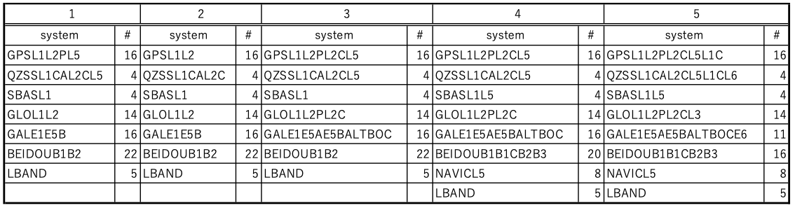
Channel configuration 5 can also receive the L6 band where the MICHIBIKI augmentation signal is broadcast and the E6 band of Galileo. Channel configuration 4 allocates many channels to Galileo and BeiDou. Only channel configurations 4 and 5 can receive Indian NAVIC (Navigation for Indian Constellation, formerly IRNSS: Indian Regional Navigation Satellite System) signals. I changed to this because channel number 5, which can receive more MICHIBIKI signals, is the best for me. Channel number 5 can receive GPS L1C signals (separate from L1 C/A signals), but cannot receive Michibiki’s L1C signals. I would be happy if I could receive Michibiki L1C instead of the 5 channels of L-Band that can only be used with a contract.
selectchanconfig 5
Running this command will reboot the receiver. At that time, the connection of the three USB ports will be lost. To connect to the USB port again, unplug and reconnect the USB cable. If you have a remote desktop connection like me, you will have to restart your Windows PC.
Also, in the initial state, the SBAS (satellite based augmentation system, read as es-bus, positioning signal, augmentation signal, and integrity signal) reception function broadcast from geostationary satellites was turned off, so I turned it on.
sbascontrol enable
With this channel configuration 5, the L6 signals of the four MICHIBIKI satellites can be observed. However, the L6 signal display appeared on my receiver only for the first PRN (pseudo random noise, unique number for separating and identifying satellite signals) 193. We look forward to future OEM729 firmware updates that will allow you to receive all Michibiki L6 signals.
Receiver control from a remote terminal
It is also possible to set the receiver from a remote terminal using telnet or nc without using a remote desktop or browser. However, since the password flows in clear text, there is a device inside the firewall and it is a function that can be used in a reliable network.
This remote control function is performed via the port ICOM. ICOM ports are prepared from 1 to 7, and TCP port numbers 3001 to 3007 are assigned by default.
First, set a password with SETADMINPASSWORD and start the ICOM port.
setadminpassword [old password] [new password]
ipservice secure_icom enable
saveconfig
The initial string of the password is the serial number of the receiver. To use it, use the telnet command or nc command to connect to port 3001, for example. A prompt such as [ICOM1] will be displayed. Enter login admin [password] before starting to use. Enter logout when you are finished using it.
It is possible not to set a password, but then anyone can set the receiver. However, considering that this password is transmitted in clear text and that the receiver can be set without a password in the browser, this password may be of little significance.
List of receiver settings
Issuing the LOG RXCONFIG ONCE command will dump all of its receiver settings. I saved this result in a file and made a setting CSV file by making full use of the vi command. Here is a part of the result of loading it into Excel.
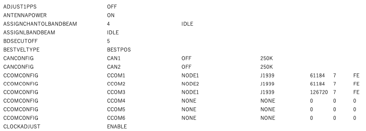
Some of these settings are not written in the manual. The manual says not to set such items. You can return the receiver settings other than the password to the factory settings by executing the FRESET command without options.
Sending RTCM message to NTRIP Caster
We can set up NTRIP configuration for performing RTK or PPP externally with this received signal, or for performing RTK or PPP with this receiver using external information. The communication port name for becoming an NTRIP Server or NTRIP Client is NCOM. This receiver has three communication ports, NCOM1 NCOM2 NCOM3, so you can input and output 3 groups of information at the same time.
Since the GNSS antenna Javad GrAnt-G5T used here is not registered in the antenna list of this receiver, this antenna information is newly registered in user_antenna_1. Also, using this receiver as an NTRIP Server, it seems that you have to determine your own coordinates in order to extract the signal to the external network. You can also use the AUTOSURVEY command to determine your own coordinates by long-term positioning, but here we gave the receiver fixed coordinates.
antennatype add user_antenna_1 JAVGRANT_G5T 2 GPSL1 3.06  1.67 50.24 0 0.00  0.47  0.79  1.06  1.06  0.97  0.62  0.29  0.00 -0.34 -0.48 -0.72 -0.76 -0.78 -0.51  0.26  1.63 0 GPSL2 0.41 -4.16 55.95 0 0.00 -1.13 -1.51 -1.38 -1.09 -0.68 -0.30 -0.17 -0.22 -0.42 -0.76 -1.26 -1.93 -2.53 -3.33 -4.13 -4.58 0
thisantennatype user_antenna_1
ntripconfig ncom1 server v1 [NTRIP Caster IPアドレス]:[ポート番号] [マウントポイント] "" [パスワード]
interfacemode ncom1 NONE RTCMV3 OFF
log ncom1 rtcm1004 once
log ncom1 rtcm1008 once
log ncom1 rtcm1020 once
log ncom1 rtcm1006 ontime 10
log ncom1 rtcm1033 ontime 10
log ncom1 rtcm1077 ontime 0.2
log ncom1 rtcm1087 ontime 0.2
log ncom1 rtcm1097 ontime 0.2
log ncom1 rtcm1107 ontime 0.2
log ncom1 rtcm1117 ontime 0.2
log ncom1 rtcm1127 ontime 0.2
log ncom1 rtcm1019 ontime 10
log ncom1 rtcm1020 ontime 10
log ncom1 rtcm1042 ontime 10
log ncom1 rtcm1044 ontime 10
log ncom1 rtcm1045 ontime 10
log ncom1 rtcm1046 ontime 10
fix position 34.44010575 132.41478407 232.784
saveconfig
Here, log ncom1 rtcm1004 once, log ncom1 rtcm1008 once, and log ncom1 rtcm1020 once are sent to the receiver, because we avoid conflicting between the old RTCM 1004, 1008, 1020 messages and the new MSM (multiple signal message). When you configure NTRIP Server on the OEM729 receiver, it automatically adds a setting to send old RTCM messages every second, so you only need to configure it once. It is set to output the antenna position for performing RTK externally, the model number of the receiver and antenna, GPS, GLONASS, Galileo, BeiDou, Quasi-Zenith Satellite orbit information (ephemeris) and the pseudo distance to each satellite.
Here, create a simple server as nc -kl [arbitrary port number of 1024 or more] on the Linux terminal, and if you connect NTRIP to this Linux terminal from this OEM729 receiver, the word HTTP/1.1 has appeared. The NTRIP Caster realized by str2str of RTKLIB 2.4.3 b33 can connect to the NTRIP Server and Client that communicate with HTTP/1.0, so here I connected this receiver to another NTRIP Caster. Then, RTK positioning was performed with RTKNAVI of RTKLIB.
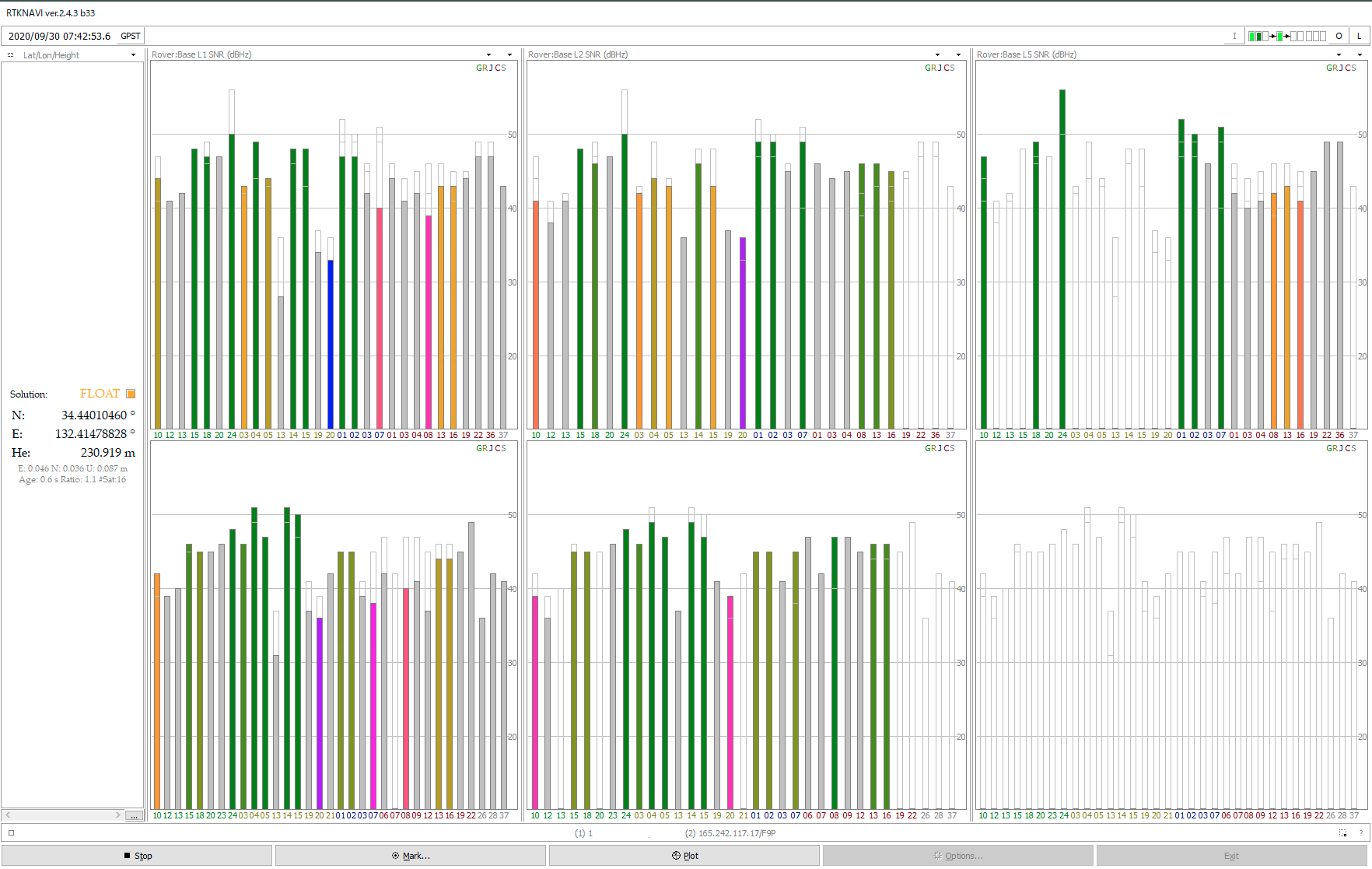
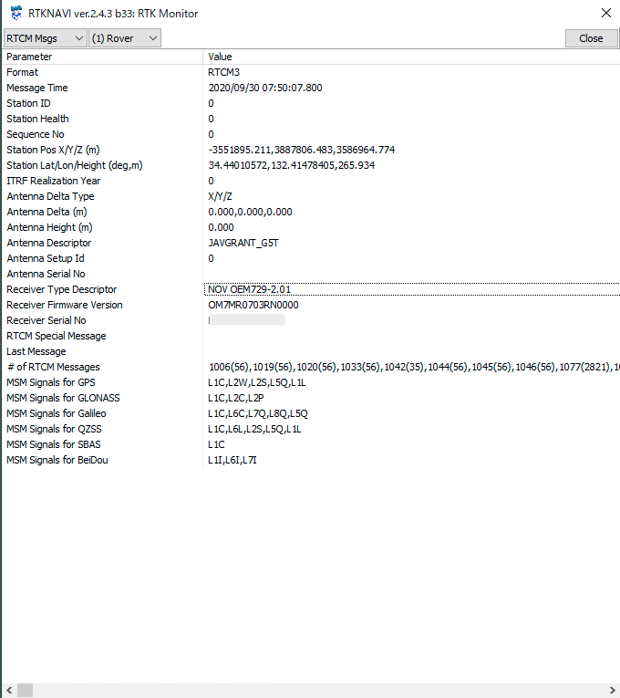
The top is the NovAtel OEM729 and the bottom is the u-blox NEO-F9P satellite signal display, and the L1 band, L2 band, and L5 band are plotted from left to right using the 3-pane display. At the OEM729 receiver, I am glad that the L5 band signal is also displayed. Also, the receiver name included in the RTCM 1033 message is NOV OEM729-2.01, and the firmware version is OM7MR0703RN0000. The serial number was also sent. In the world of GNSS, the receiver serial number may be public.
It was possible to send RTCM messages to a USB port instead of the NCOM port, and it was also possible to use the RTKLIB strstr to convert this USB port output to a TCP stream. However, when I set the ICOM port to output RTCM messages, nothing was output.
It’s a lot of fun to use RTKLIB and GNSS receivers. I enjoyed a moment of peace in my daily life when I was busy preparing for online classes.