Assembling the Electric Crawler (Part 3)
Introduction
I’m assembling an electric crawler. With the work so far, I was able to assemble it, but it took some trial and error to get it to work. I’ve finally managed to get it to operate automatically.
Autonomous operation with minimal configuration
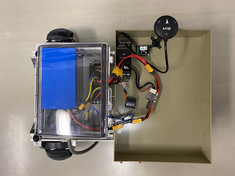
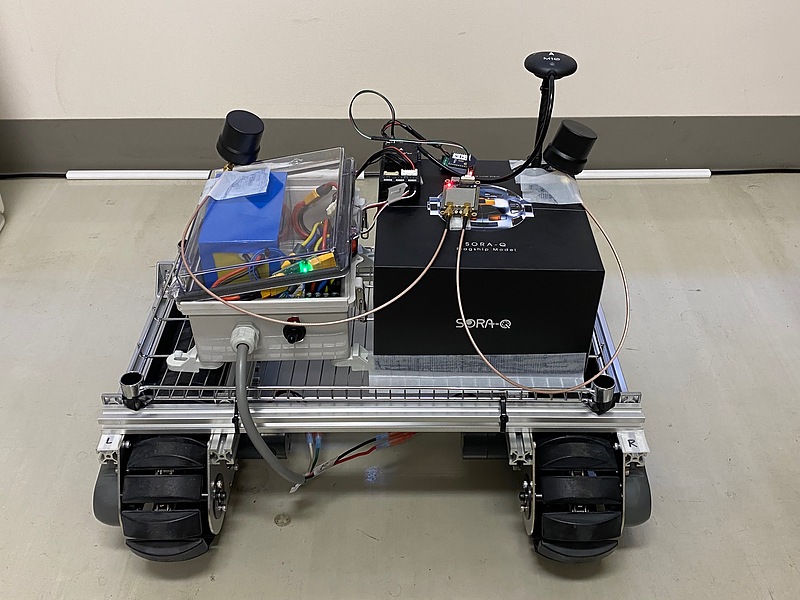
The crawler body consists of a CuGo V3 with an integrated motor and battery, an automatic control microcomputer Pixhawk 6X, and a GPS antenna.
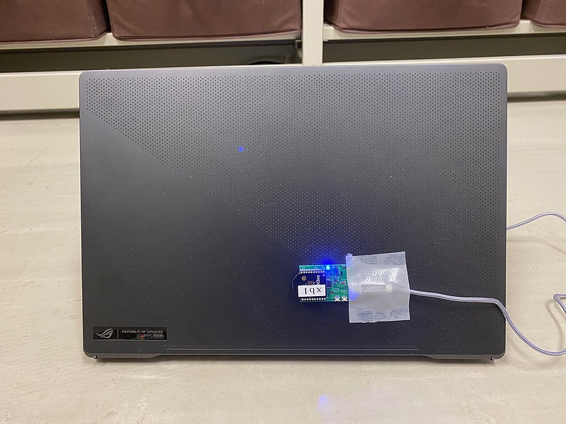
A computer with Mission Planner installed is also required to set the driving course, provide driving instructions, and monitor the sensor status. The crawler body and the laptop are connected via serial ports via ZigBee wireless. Since you will be chasing the crawler while holding the laptop, I attached the ZigBee module to the back of the laptop so that the wireless module does not get in the way.
As an initial step, I decide on the equipment placement, securing it in place with tape.
The crawler’s microcontroller uses the GPS receiver and the inertial navigation sensor inside the microcontroller to determine the direction in which it should move. Before driving, the inertial navigation sensor (IMU: Inertial Measurement Unit) needs to be calibrated. This calibration is performed by randomly rotating the IMU itself, so if the microcontroller is fixed firmly, it will be difficult later. The GPS receiver (written as M10) also has an IMU built in, so when calibrating the IMU, this GPS receiver is also rotated randomly and widely.
After calibrating the IMU, I attached the microcontroller to the crawler, but an error indicating an excessive magnetic field was displayed on the Mission Planner, and I was unable to put it into operation mode (arm mode). It seems that the crawler body is magnetized. To separate the microcontroller from metal parts, I raised the microcontroller with a cardboard box. However, I was unable to resolve the error indicating a data discrepancy between the IMU in the microcontroller and the IMU in the GPS receiver.
I took the crawler outside to check its operation. Even when the crawler was stationary, it was displayed as moving on the computer due to insufficient positioning accuracy. Even when it was in automatic operation, it started moving in random directions, and it was necessary to stop it by turning off the power.
Autonomous driving using RTK and dual-antenna GPS receiver
Therefore, I connected a GPS receiver that can measure direction using two antennas, Unicore Communications’ UM982, to the GPS2 port of the Pixhawk 6X microcontroller. These were also temporarily fixed with tape. This two-antenna receiver estimates the positional relationship between the antennas through continuous positioning, and can estimate the crawler direction even when stationary. RTK positioning is also possible using the RTCM format. In Mission Planner, I turned off direction estimation using the IMU and turned on direction estimation using the GPS receiver.
A wireless gamepad is also connected to the PC. Mission Planner also allows manual control using the gamepad. This makes it easier to move the crawler. In the end, you will be carrying both the laptop and the gamepad while chasing the electric crawler during your experiments. Please note that Bluetooth-connected gamepads cannot be used with Mission Planner.
Since the accuracy of single positioning is insufficient, local RTK is used for positioning. RTK reference station information is set on Mission Planner, and augmentation information is also received on the computer running Mission Planner. Tethering with a smartphone is also required to use RTK.
While measuring position outdoors, move the crawler body and set waypoints (traveling points) on the Mission Planner at any point. After that, transfer the waypoints from the Mission Planner to the crawler microcomputer and issue instructions for automatic driving.
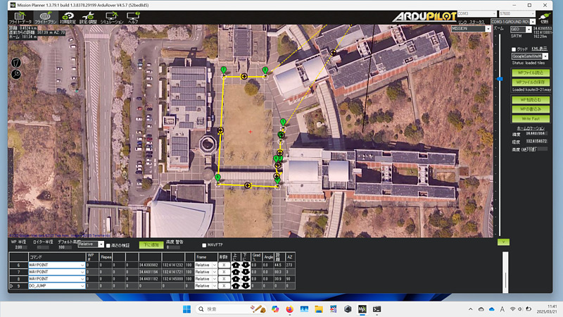
In fact, part of the driving route was on the edge of the road, and I almost came into contact with a ground structure. Each time this happened, I had to turn off the power to the main unit and stop it, which took a long time to complete the course. I should have set waypoints in advance and just checked them on site. I also needed a contact stop sensor and a remote stopping method.
Conclusion
For the crawler to run automatically, not only positioning accuracy but also direction estimation is required. Using RTK and a two-antenna receiver, I was able to run it automatically. Manual operation with a gamepad also helped to improve the efficiency of the experiment. I gave up on using the IMU. I would like to further improve the crawler by considering stopping it on contact, stopping it remotely, and considering power supply and waterproofing methods.
Related article(s):
- Assembling the Electric Crawler (Part 2) 15th October 2024
- Assembling the Electric Crawler (Part 1) 11st October 2024