Assembling the Electric Crawler (Part 1)
Introduction
I wanted to try making an autonomous robot as an application of GNSS high-precision positioning. The Institute of Positioning, Navigation and Timing of Japan holds a QZSS/GNSS Robot Car Contest every October, and I would like to try it someday.
I didn’t how to make a robot, but I found an article on “Making a High-Precision cm-Class GPS Autonomous Driving Robot” in the Summer 2024 issue of Toragi Jr. (in Japanese), a booklet for students and new engineers. Now you can start making an electric transport vehicle (crawler). I tried out what was written in this book.
Configuration
In order to assemble an autonomous crawler, there are many things to consider, including not only positioning, but also electrical signal control based on the positioning results, motor control based on electrical signals, construction to store the equipment, etc. The above article also includes know-how such as the product names of the equipment to be introduced, step-by-step operation check methods, and software settings, which is very helpful.
Here, I slightly adapted the method from the article above to help me think about it. The equipment I used is as follows:
- Electric crawler CuGo V3 Complete Kit (as in the article)
- Flight controller Holybro PixHawk 6X (PX4 2.4.8 in the article)
- GNSS receiver u-blox M10N for PixHawk (with buzzer, safety switch, and GPS1 connector. Planned to be used as a secondary GNSS receiver. GNSS receiver, buzzer, and safety switch are prepared separately in the article)
- Power module PM02D (connected to the connector in the middle of the standard power cable, provides 5.2V power supply to PixHawk and voltage monitor via I2C. In the article, DC-DC converter is prepared separately)
- Open source software for control ArduPilot and Windows PC (as in the article)
For items 2, 3, and 4, I used the Standard Set M10 GPS set from the Holybro Pixhawk 6X Kit sold on AliExpress.
The following equipment will be added in the future:
- Dual-antenna GNSS receiver Unicore Communications UM982 Kit TOP982 (To be used as the primary GNSS receiver. In the article, Septentrio mosaic-H)
- Serial port wireless XBee S2C (In the article, the telemetry unit for PixHawk2)
In this configuration,
- coordinates are measured by the GNSS receiver,
- heading is measured by the GNSS receiver and the IMU (inertial measurement unit) in PixHawk,
- attitude is measured by the IMU sensor in PixHawk,
and then read into PixHawk. The interface is standardized, so connecting the devices is as simple as plugging in the connector.
The route coordinates and movement distance are calculated using the Mission Planner software from ArduPilot, which runs on a Windows PC. The PixHawk is connected to the PC via USB or radio telemetry.
On the other hand, the motor control format used by PixHawk is PWM (pulse width modulation). Three wires are used for each control signal: power, ground, and signal. The output format of manual wireless flight controllers (transmitters) is also PWM. This interface is also standardized. If the electric crawler can be controlled using a wireless transmitter receiver, it can be automated by switching the wiring from the transmitter receiver to PixHawk.
A motor driver (ESC: electric speed controller) is used to control the motor with this PWM output. The ESC has a connector to receive the PWM signal, as well as a large connector that can handle the large current required to drive the motor.
Electric Crawler
So I purchased the CuGo V3 Complete Kit, which includes two electric crawler motor units (CuGo V3), battery, battery charger, ESC, transmitter, and transmitter receiver, and is set up so that the crawlers can be remotely controlled using the transmitter.
To use this kit, you need to assemble the motors on the chassis, but this process was a good practice for expanding the kit yourself. Screws and an aluminum frame are also included. The motors are two IP4X waterproof brushed motors, one for each side, with a maximum load capacity of 80 kg. They run on a built-in 24-volt rechargeable battery. The two ESCs, battery, and radio receiver are pre-connected and housed in a waterproof box, but you have to make your own connections between the ESCs and the motors.
There are higher-end models of this CuGo V3,
- CuGo V3i (brushless motor, not waterproof) and
- CuGo V4 (brushless motor, IP65 dustproof and waterproof).
The specifications stated that the control interface of these was USB or TTL, so I quickly eliminated them from my list of purchases. However, these have a built-in radio control receiver board that can receive radio control signals, and it is possible to switch between this receiver and the control Raspberry Pi Pico, so it may be possible to set it to receive the PWM signal from the PixHawk. The V4’s brushless motor and dustproof and waterproof features are also attractive, but it is somewhat expensive.
The V3 Complete Kit came with a radio control system, was set up so that I could control the crawlers right away, had little chance of failure, and was suitable for my purposes as it was a good way to learn about mechanism expansion. I’m glad I purchased the model recommended in the article above.
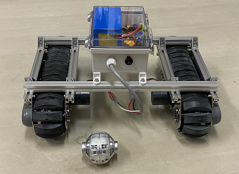
This V3 complete kit is pre-configured so that the left wheel can be controlled by the front and rear of the right stick of the transmitter, and the right wheel can be controlled by the front and rear of the left stick. This transmitter can receive information from the left and right of the stick, the push of the stick, and other switches on the transmitter at the transmitter receiver. If you connect the transmitter receiver output to the PixHawk PWM input and set up Mission Planner, you might be able to do some interesting things.
PixHawk and Mission Planner
The PixHawk 6X can receive two GNSS inputs and can also connect to wired Ethernet. In addition, the PixHawk 6X has a wealth of I/O ports, including three telemetry ports, two CAN (controller area network) ports, one I2C port, two ESC ports, eight PWM I/O ports, and four external input ports. The PixHawk 6X I purchased also came with connectors. To attach the PixHawk 6X to the chassis, use double-sided tape.
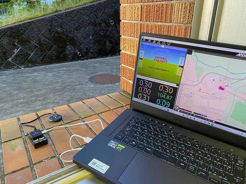
First, install the ArduPilot Mission Planner software on Windows PC. Here, I used the standard Windows PC package manager winget.
winget install "mission planner"
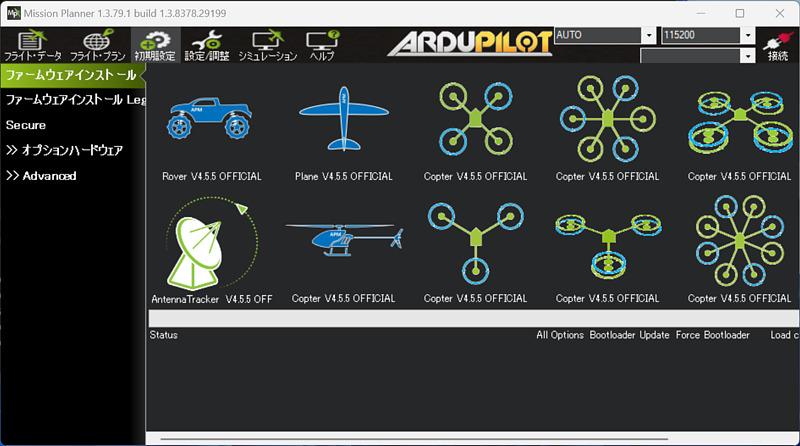
Next, connect the M10N receiver to the GPS1 connector of the PixHawk 6X and the USB cable to the PC. The first thing to do is to start Mission Planner and install the firmware to the PixHawk 6X. Here, I use Rover V4.5.5 Official as the firmware.
Two serial ports appeared on the PC. Select one of the serial ports from the pull-down menu and press the connect button in the upper right corner, and an illustration of a ROVER will appear on the map. I placed the M10 receiver on a windowsill and continued positioning. It took about 10 minutes for the correct position to be displayed. The artificial horizon in the attitude indicator (AI) in the upper left corner is also cool, like the glass cockpit of an aircraft. If I tilt the PixHawk body, this artificial horizon moves and the altitude display scale on the right changes.
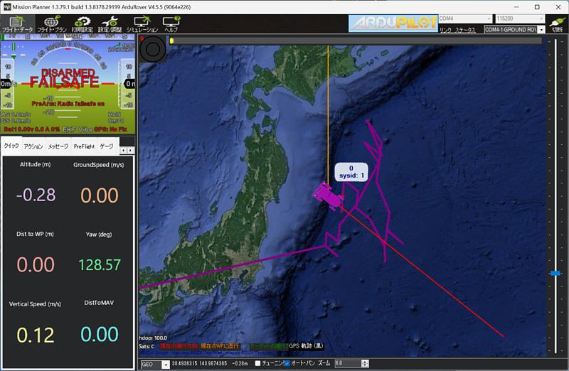
You can specify a route to travel by right-clicking on the map. It is currently in disarm (safe) state, but if you arm (start) it in the action menu on the bottom left, automatic control will begin.
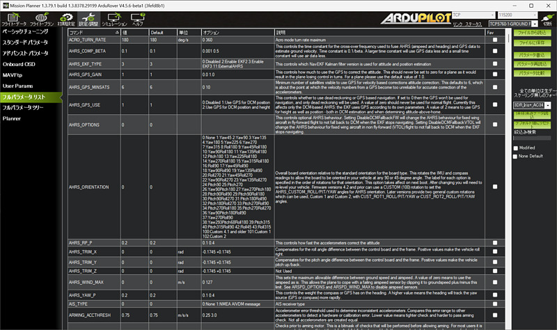
The operation of PixHawk is set from the full parameter list screen. Telemetry, secondary GNSS receiver, left and right motor wiring, etc. can also be set here. Depending on the settings, raw data from the primary GNSS receiver can also be interpreted. Mission Planner also has a setting item for the NTRIP client, and the GNSS satellite number and signal strength were displayed by specifying the address of the NTRIP caster. RTK positioning seems to be possible.
I’ll try a bit harder and try to make it autonomous.
Conclusion
I assembled an electric crawler and tried using ArduPilot’s PixHawk and Mission Planner. There were many things I only learned by doing things myself, such as mechanical construction and crawler control, so I’m glad I took on the challenge. I’d like to be able to control the crawler based on GNSS positioning.
Related article(s):
- Assembling the Electric Crawler (Part 3) 23rd April 2025
- Assembling the Electric Crawler (Part 3) 21st October 2024
- Assembling the Electric Crawler (Part 2) 15th October 2024