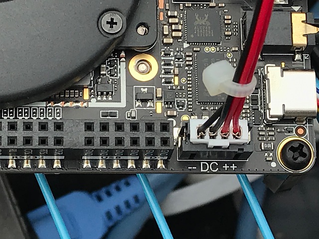
Powering to Latte Panda with JST PH 4P connector
It is convenient for experiments if there is a Windows 10 microcomputer that we do not have to connect a display and keyboard.
I use Latte Panda Alpha 864 for such a purpose, but we need the powering from the USB-C port. In most cases, we use USB-C’s 15V power delivery (PD) mode for powering a Latte Panda microcomputer. However, continuous use of the USB-C PD power supply in an outdoor environment would be difficult in terms of reliability, so I decided to supply power from the power connector on the Latte Panda.
The Latte Panda company has been announced how to supply power using this JST PH 4-pin connector. The voltage is ranging 10 to 15 V, and the current is 3 A at maximum.
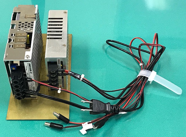
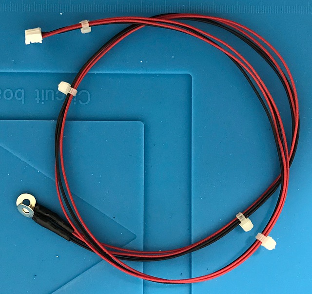
I chose a power supply RWS150B-12 of TDK Lambda, Co. Ltd. and we can buy from Auks Dash in Japan. According to the operation manual, it is a 13-A power supply. We may choose such power supply for considering output derating at an environmental high temperature. The rated current of this JST PH contact is 2 A when using the thickest wire available of AWG# 24 (the smaller the number, the thicker and more current can flow). For covering the maximum current of 3 A of Latte Panda, it is necessary to connect two wires to each terminal of the positive and negative.
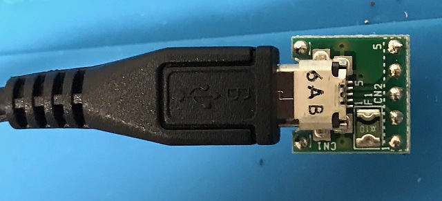
I also prepared a USB type 5V power supply. When the micro USB cable was disassembled, four wires, red, black, green, and white, wrapped in shielded wires appeared. The red line was plus 5 V and the black line was minus.
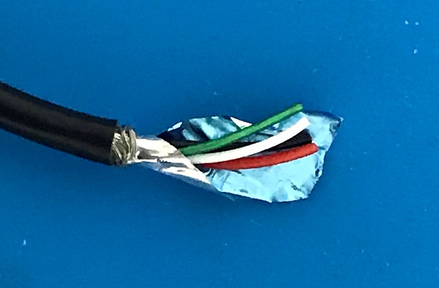
[Micro USB Connector DIP Kit] (http://akizukidenshi.com/catalog/g/gK-10972/) was used for continuity inspection after cable processing.
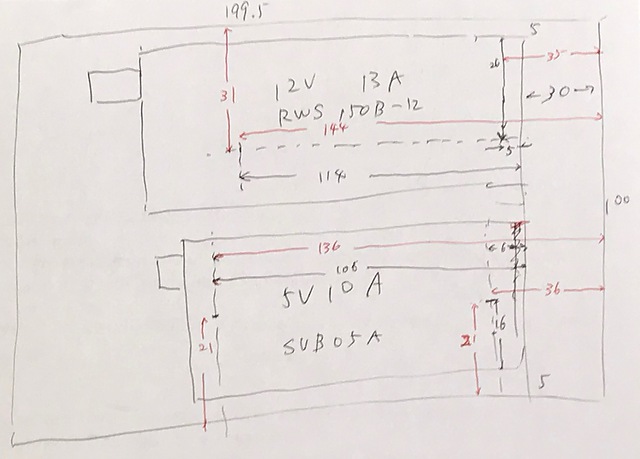
The power supply must be installed in the correct orientation. According to page 14 of the above operation manual, the standard mounting direction is vertical. Also, according to page 13, a space of at least 15 mm is provided on the left and right for heat dissipation. Therefore, these power supplies were installed 5 mm left and right of the metal plate. The positions of the screw holes on the bottom were measured with calipers and drilled.
The picture below is a completed one. After soldering, use a heat shrink tube to insulate and wire the connection neatly. This may seem like a waste, but this is necessary for high reliability.