GPS chip antenna
Introduction
Smartphones utilize chip components to achieve miniaturization. This miniaturization trend is also applied to GPS antennas.
On the other hand, it is known that by arranging multiple antennas at half-wavelength intervals to form an array, and by optimizing the reception method, it is possible to receive radio waves only from a specific direction. Array antennas are expected to have the ability to cancel out interfering radio waves. The smaller the antenna, the greater the freedom in array design.
Here, as a preliminary study of GPS array antennas, I measured the characteristics of a GPS chip antenna.
Characteristics of a single antenna
GPS chip antennas can be purchased from electronics retailers for around 100 yen each.
While an amplifier to supply sufficient power to the receiver and a filter to remove adjacent cell phone signals are essential for actual use as an antenna, here I examine the characteristics of the chip antenna alone.
Ideally, a printed circuit board with a circuit that achieves an impedance of 50 ohms should be created for measurement, but here I will wire the chip antenna to both ends of an SMA connector and measure it by connecting it to a network analyzer.
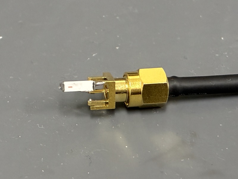
The network analyzer used here has two terminals, allowing for transmission via port 2 while receiving via port 1 (S21 parameter measurement), or simultaneous transmission and reception via port 1 (S11 parameter measurement). Here, the network analyzer is set to S11 parameter measurement mode, and the extent to which the radio waves transmitted from the network analyzer return to the network analyzer via the antenna is measured.
The following is a screenshot of the network analyzer screen.
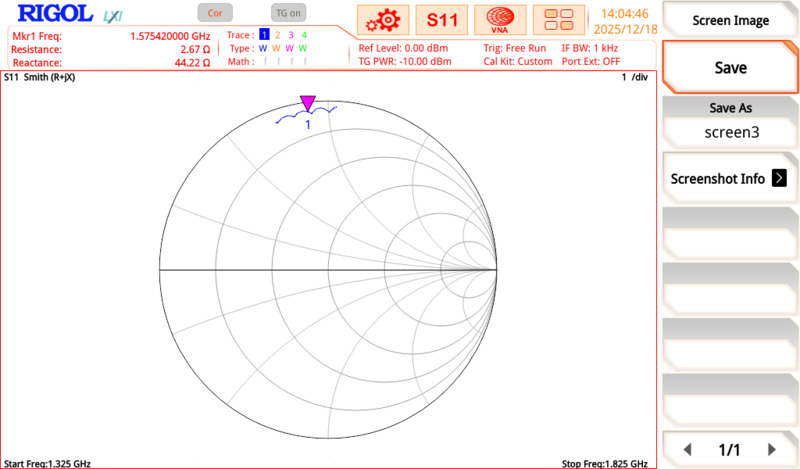
The center frequency was set to that of the GPS L1 signal (1575.42 MHz), the measurement frequency bandwidth (span) was set to 500 MHz, and a marker (orange triangle) was set to determine the numerical characteristics at that center frequency. At this time, the impedance at the marker frequency was 2.67 + 44.22 j ohms. Impedance is usually expressed as a complex number.
If no radio waves return to the network analyzer, it can be assumed that all of these radio waves were radiated from the antenna. In that case, the impedance would be 50 + 0 j ohms. However, this impedance is significantly far from the target impedance.
This diagram is called a Smith chart, and its characteristics are read based on the center of the circle and the thick lines on either side indicating the diameter. The center of the circle represents 50 + 0j ohms, and the lines on either side represent the real part of the impedance (resistance). The left end of the line is 0 + 0j ohms, and the right end is infinity + 0j ohms.
The arcs extending upwards and downwards from the right end represent the imaginary part of the impedance (reactance). The upward arc represents positive reactance, and the downward arc represents negative reactance. The resistance can range from 0 ohms to infinity, and the reactance from negative infinity to positive infinity. Therefore, the closer the measurement trajectory is to the center of the circle, the better; the antenna should be adjusted so that it reaches the center of the circle at the target frequency. The Smith chart is a great invention that can concisely represent impedance characteristics.
However, the characteristics of this antenna are not good at all.
Chip antennas require a grounding plate
Though I didn’t think it could be, when I touched one side of the chip antenna with my finger, its performance improved.
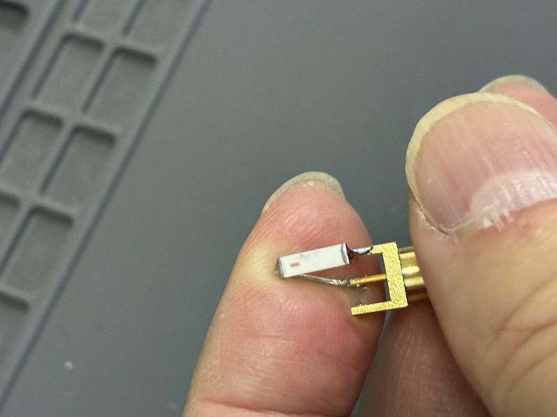
The reactance component has decreased, and the resistance component is approaching 50 ohms. Moreover, even when sweeping the frequency across a 500 MHz bandwidth, the characteristics hardly changed. Amazing.
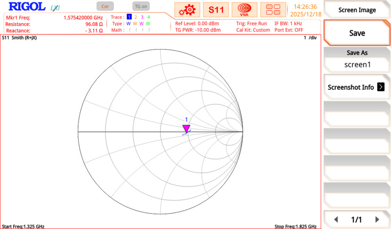
Chip antennas should not be used with point-to-point wiring. Chip antennas mounted on a double-sided circuit board with a proper grounding plate seem to perform quite well.
Conclusion
When using chip antennas, it was necessary to create a printed circuit board with matched impedance. I’ll consider amplifiers and filters.