Azimuth determination of installing survey grade GNSS antenna
Why we have to be aware of the north direction of the antenna
In order to perform satellite positioning on the order of centimeters, the electrical center position (phase center) of the antenna must be taken into consideration.
Microstrip antennas, which are widely used as antenna elements inside the GNSS antenna housing, have zero ohm impedance at the physical center. Therefore, a hole is made from the back surface of the antenna element at a point where the appropriate impedance (usually 50 ohms) is separated from the physical center position of the antenna element by a certain distance, or at the end of the antenna element assuming impedance conversion. The structure is such that the antenna element surface is opened and soldered to supply power. If the antenna element is placed in the center of the antenna housing in order to make the antenna housing as small as possible, there will be a horizontal positional difference between the physical antenna center and the antenna phase center.
Furthermore, in such a GNSS antenna, multiple antenna elements are housed in the same housing in order to observe multiple frequency bands at the same time. Microstrip antennas have a structure that spreads horizontally. In order to compactly accommodate multiple antenna elements in the housing, multiple antennas are stacked in the vertical direction, so there is a positional difference in the phase center between these antennas, especially in the vertical direction. After all, the 3D phase center position of the antenna will be different for each frequency band used.
In addition, the antenna housing is equipped with a radome (originally from radar dome) to protect the antenna element. In addition to the elevation phase characteristic of the antenna element itself, there is a phase fluctuation in the elevation direction of the arrival of radio waves due to the radome. Microstrip antennas also have phase characteristic differences in the azimuth direction called the electric field surface (E-plane) and magnetic field surface (H-plane). However, it is considered that the phase fluctuation in the azimuth direction is sufficiently small because the power is supplied by adding a phase difference of 90 degrees at the two points of the antenna element to generate circularly polarized waves (turnstile antenna structure).
Therefore, when using a survey class GNSS antenna, install the antenna in the north direction specified by the antenna manufacturer. Then, when performing positioning such as RTK, the antenna phase center position and phase fluctuation data are used to correct and align the phase fluctuations due to the phase center and elevation angle in different frequency bands before analysis.
Azimuth direction in antenna installation
For such correction, the antenna reference point (ARP) is determined, and the displacement from ARP to the phase center offset (PCO) and the horizontal from the zenith are determined for each frequency used. The phase fluctuation characteristics (PCV: phase center variation) up to are measured. These data are published on the National Geodetic Survey (NGS) website of the National Oceanic and Atmospheric Administration (NOAA) and on the antenna manufacturer’s website.
The antenna Javad GrANT-G5T that I use is managed by the model number JAVGRANT_G5T. Pointing to “Browse Antenna Information by Company Brand and Model” on the NGS Antenna Calibration page, and seeing “JAV - Javad, Inc.”, we can find the Drawing of this model number. Then we can find how to install the antenna as RXC to North. It means the receiver antenna connector (RXC) should be installed facing north. ARP was on the bottom of the antenna. “NONE” written here means that there are no options to improve antenna performance such as a ground plate attached to the antenna or a choke ring that suppresses the mixing of reflected waves on the ground.
Antenna phase
To obtain the phase variation characteristics (PCV) for this antenna JAVGRANT_G5T from the NGS website, click `ʻANTINFO`` (antenna information) in the “Calibration” column of the model number.
     1.4            G                                       ANTEX VERSION / SYST
A                                                           PCV TYPE / REFANT
This calibration extracted from composite ngs14.atx.  See   COMMENT
the composite file ngs14.atx for more information.          COMMENT
                                                            END OF HEADER
                                                            START OF ANTENNA
JAVGRANT_G5T    NONE                                        TYPE / SERIAL NO
FIELD               NGS                      4    04-MAR-14 METH / BY / # / DATE
     0.0                                                    DAZI
     0.0  80.0   5.0                                        ZEN1 / ZEN2 / DZEN
     2                                                      # OF FREQUENCIES
NGSRA_2120                                                  SINEX CODE
CONVERTED FROM RELATIVE NGS ANTENNA CALIBRATIONS            COMMENT
   G01                                                      START OF FREQUENCY
      3.06      1.67     50.24                              NORTH / EAST / UP
   NOAZI    0.00    0.47    0.79    1.06    1.06    0.97    0.62    0.29    0.00   -0.34   -0.48   -0.72   -0.76   -0.78   -0.51    0.26    1.63
   G01                                                      END OF FREQUENCY
   G02                                                      START OF FREQUENCY
      0.41     -4.16     55.95                              NORTH / EAST / UP
   NOAZI    0.00   -1.13   -1.51   -1.38   -1.09   -0.68   -0.30   -0.17   -0.22   -0.42   -0.76   -1.26   -1.93   -2.53   -3.33   -4.13   -4.58
   G02                                                      END OF FREQUENCY
                                                            END OF ANTENNA
G01 represents the GPS L1 frequency band, G02 represents the GPS L2 frequency band, and this information includes two frequency bands. From this file, we can see that the altitude of the L1 band antenna from ARP is 50.24 mm, the altitude of the L2 antenna is 55.95 mm, and there is an altitude difference of about 5 mm between the two antennas. NOAZI (non-azimuth-dependent pattern, that is, azimuth-independent phase fluctuation correction, defined as here. The 17 numbers represent the amount of phase variation correction in millimeters every 5 degrees from the zenith to the horizontal.
Save this information to a file and specify the file with analysis software such as RTKLIB in order to correct the antenna phase and align the phase centers in different frequency bands for analysis.
There is also ngs14.atx, which also contains many other antennas, but I avoided direct links due to the large file size of 16MB.
https://www.ngs.noaa.gov/ANTCAL/LoadFile?file=ngs14.atx
Settings in RTKLIB
Here, the satellite PCV file `ʻigs14.atx`` is also downloaded from the CDDIS (Central Dynamics Data Information System) website.
In RTK NAVI in RTKLIB, check the checkbox of Antenna Type in Options-> Positions and write JAVGRANT_G5T NONE.
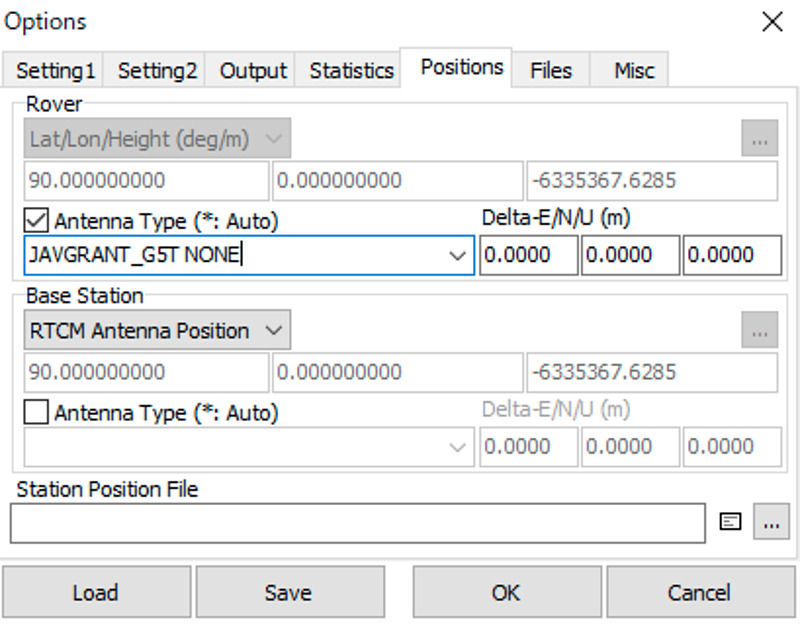
If the RTK reference station is broadcasting an RTCM 1007 (Antenna Descriptor), RTCM 1008 (Antenna Descriptor and Serial Number), or RTCM 1033 (Receiver and Antenna Descriptor) message, It is possible to automatically set the antenna type by filling the field to asterisk *. I have set my RTK reference station broadcasting RTCM 1033 messages.
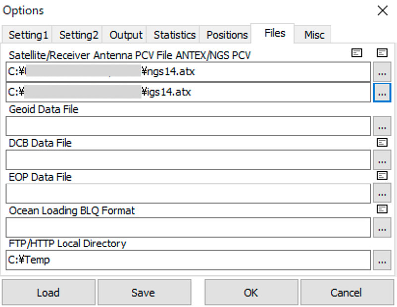
Next, set the antenna PCV by specifying ngs14.atx and `ʻigs14.atx`` in Options-> Files at RTKNAVI.
RTK reference station setting with RTKLIB str2str
If the RTCM 1033 message can be broadcast on the reference station, the antenna type is automatically set for each reference station on the receiver side, which is convenient. The reference station coordinates are broadcast in the RTCM 1005 message. My reference station uses str2str of RTKLIB 2.4.3 b33 to broadcast RTCM 3 messages from u-blox ZED-F9P raw messages and sends them to NTRIP Caster with the following options:
str2str \
    -in  [serial port of u-blox ZED-F9P receiver]#ubx \
    -out [hostname of the NTRIP Caster]#rtcm3 \
    -msg 1005(10),1033(10),1019,1020,1042,1044,1045,1046,1077(1),1087(1),1097(1),1107(1),1117(1),1127(1) \
    -p   34.44010565 132.41478259 233.057 \
    -i   "u-blox NEO-F9P,HPG1.13,N/A" \
    -a   "JAVGRANT_G5T NONE,N/A,0"
The -p option denotes the latitude/longitude/altitude of the reference station, the -i option specifies the receiver type, firmware version, and serial number, and the -a option is for the antenna type, serial number. and the point number (integer). I wrote the serial number as (N/A: not available).
My NTRIP Caster is realized using str2str.
From now on, I would like to confirm the effect of the antenna phase variation setting.