Assembling the Electric Crawler (Part 3)
Introduction
To create a GPS electric crawler, we will wirelessly connect the automatic control computer Holybro PixHawk 6X and a Windows PC using ZigBee. Wireless communication means that there is no need to install a Windows PC on the crawler.
ZigBee XBee3 configuration
In this configuration, PixHawk and Mission Planner running on a Windows PC work together to automatically control the crawler. Here, we will make the USB-C cable that connects the two wirelessly. By connecting a radio to the telemeter (TELEM1) port of PixHawk, the two can be made wireless.
The ZigBee introduced here is XBee3 from Digi XBee. For this wireless connection purpose, the previous generation XBee2 (S2C) is sufficient. At the time of purchase, XBee3 was cheaper than XBeeS2C, so I chose XBee3. XBee3 is upwardly compatible with XBeeS2C and also includes MicroPython.
Here’s what I purchased for this wireless connection:
- XBee3 wireless module 3 sets
- XBee USB interface board kit 2 sets
- 2.54mm pitch conversion board for XBee 1 set
Two sets of wireless modules are enough, but I added a spare set for setting practice. While assembling the USB interface board, I disassembled one end of the 6-pin connector cable that came with the PixHawk 6X and connected it to the XBee pitch conversion board.
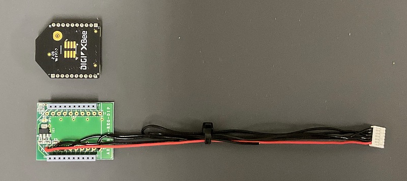
The connections are as follows:
| PixHawk 6X | XBee3 | note |
|---|---|---|
| 1 (+5Vcc) | 1 (Vcc) | |
| 2 (TX) | 3 (Din) | |
| 3 (RX) | 2 (Dout) | |
| 4 (CTS) | NC (no connection) | フローコントロール不可のため |
| 5 (RTS) | NC (no connection) | フローコントロール不可のため |
| 6 (GND) | 10 (GND) |
Meanwhile, attach a jumper pin to the pin header of the USB interface board to provide USB bus power.
Attach an XBee to each of the two USB interface boards. Then, configure each XBee one by one using the Digi XCTU software installed on the Windows PC. When scanning for devices, you will be asked for a baud rate. I chose either the default 9600 bps or 57600 bps, which I will use going forward. Once you have found the connected device, press the add button to add the device.
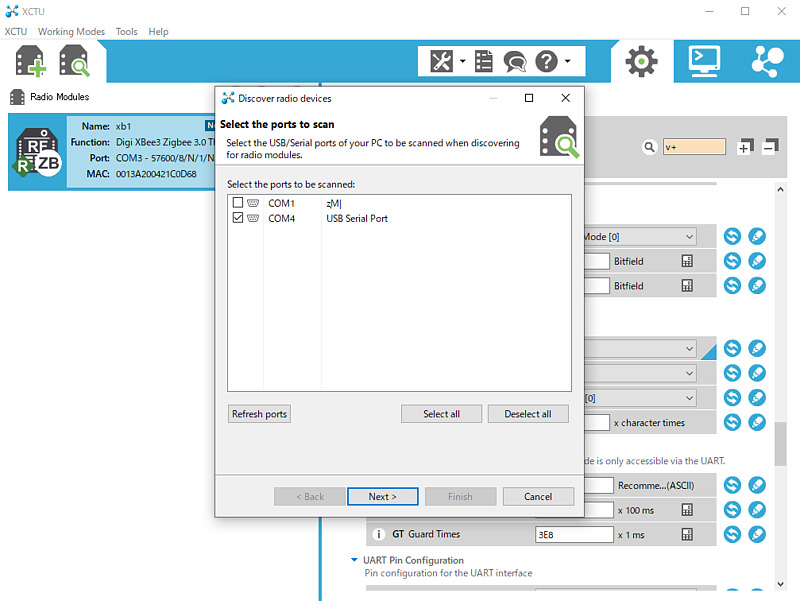
For ZigBee, set one to Join Network and the other to Form Network with Device Role CE. For this combination of ZigBee devices, the ZigBee setting example on the ArduPilot official website may not work (in Japanese), so here I set the PC side to Join Network and the PixHawk side to Form Network.
The items that were changed from the default values for each XBee3 are as follows. Note that the MAC address of the other party shown here is mine, and I confirmed it by connecting to XCTU.
| 設定 | PC側 | PixHawk側 | note |
|---|---|---|---|
| ID | 1234 | 1234 | arbitrary unsigned integer value |
| NI | xb1 | xb2 | arbitrary string |
| CE | Join Network | Form Network | |
| BD | 57600 | 57600 | changed the baudrate from 9600 bps to 57600 bps |
| D7 | 0 | 0 | turns off flow control |
| DH | 13A200 | 13A200 | The upper MAC address of the other XBee (seems to be fixed) |
| DL | 421D74B2 | 421C0D69 | The lower MAC address of the other XBee (the string following 13A200) |
Each time you enter a setting value, press the pencil button to write the setting value to the device.
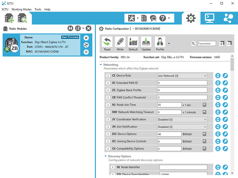
Once the settings are complete, confirm that communication is possible between the two ZigBee modules. I connected these two ZigBee modules to two Macs and confirmed that bidirectional communication was possible using screen /dev/tty.usbserial-... 57600. The ... part is the specific name of the serial port, but it can be completed by pressing the tab key in the zsh shell. To end the screen command, press Ctrl-a k.
Setting up Mission Control
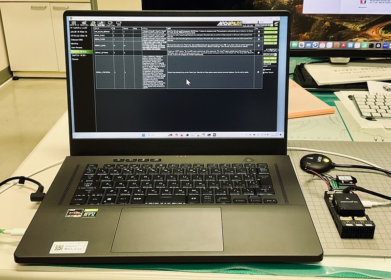
Connect the ZigBee module that has been configured on the PC side to a Windows PC and start Mission Control. The method for configuring ZigBee in Mission Control is as described on the official ArduPilot website. To turn off flow control, change BRD_SER1_RTSCTS from 2 to 0 in Settings/Adjustments→Full Parameter List.
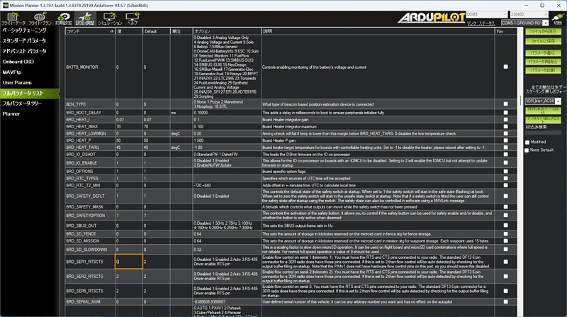
SERIAL1_PROTOCOL worked even when left as the default 2 (MAVLink 2).
Connecting ZigBee to PixHawk
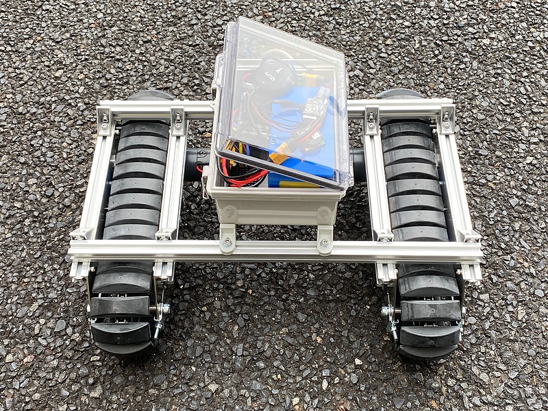
Then, connect the ZigBee module with the PixHawk settings to the pitch conversion board, connect this board to the TELEM1 port of the PixHawk, connect the PM02D to the POWER1 port of the PixHawk, and connect the GPS unit to the GPS1 port. As the amount of equipment increased, it could no longer fit into the waterproof box of the CuGo V3 Complete Kit. It became necessary to increase the size of the waterproof box.
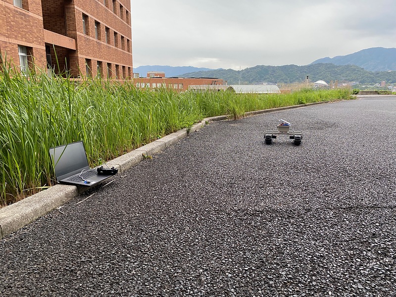
I took this equipment outside and did a test run with the radio. Since I haven’t connected the PixHawk to the ESC yet, I can’t control it automatically with ArduPilot, but I was able to get a feel for it.
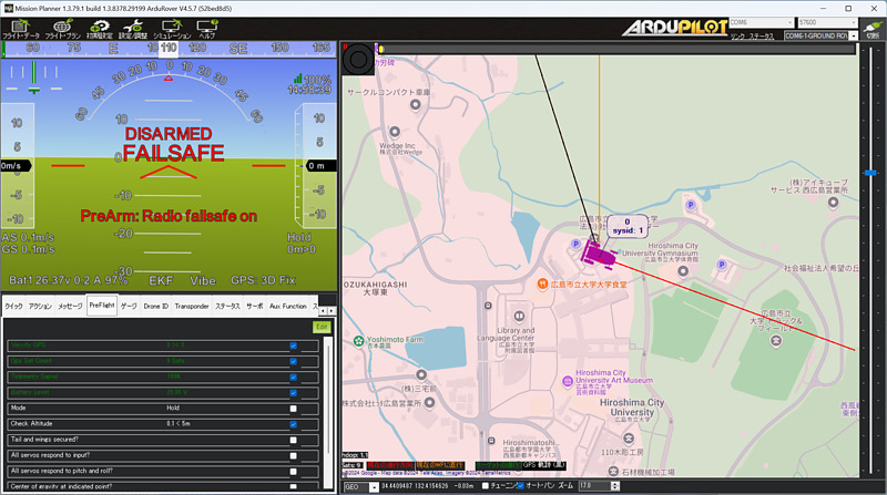
I specified the ZigBee port as the serial port for Mission Planner on my Windows PC, pressed the connect button, and PixHawk information was displayed via ZigBee. I was happy to see battery information, GPS information, and other information displayed on Mission Planner.
Conclusion
I made the PixHawk 6X and Windows PC wireless via ZigBee. In the future, I would like to connect the ESC and PixHawk and try automatic control with ArduPilot.
Related article(s):
- Assembling the Electric Crawler (Part 2) 15th October 2024
- Assembling the Electric Crawler (Part 1) 11st October 2024